


Page: 48
Service Guide ML520/521
Chapter 2 Principles of Operation
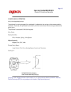
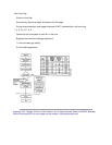
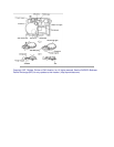
Printhead Operation
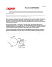
When the printhead is idle, the armature is attracted to the permanent magnet. The print wires, which are
attached to each armature, are then concealed inside the wire guide.
When a signal to print a character is received, current flows through a coil. The magnetic field generated
by the coil opposes the magnetic field between the armature and the permanent magnet. The armature is
then driven in the direction of the platen by the force of the armature spring. The print wire (which is
attached to the armature) protrudes from the tip of the wire guide and strikes the paper through the ribbon.
This prints a dot on the paper.
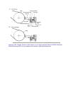
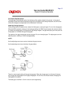
As the armature gets closer to the electrode of the analog sensor, the capacitance between them
increases and a small amount of current flows. This current is amplified and sent to the logic control LSI to
indicate armature activity. In order to attain optimum drive time, this information is transferred to the MPU.
The MPU continually modifies the head gap to maintain the optimum drive time condition.
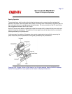
The analog sensor element monitors all of the pins. The difference in pin stroke due to the curvature of
the platen is compensated for at the logic control section of the printhead and is not transferred to the
MPU.
After the character has been printed, the permanent magnet attracts the armature and the print wires are
retracted into the wire guide.