


Page: 98
Service Guide ML520/521
Chapter 3 Maintenance & Disassembly
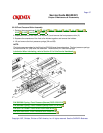
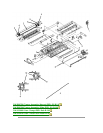
3.2.29 Tractor Assembly
1. Perform these procedures:
3.2.01
, 3.2.06 , 3.2.07 , 3.2.16 , 3.2.17 , 3.2.19 , 3.2.20 ,
3.2.22 , 3.2.23 , and 3.2.24 .
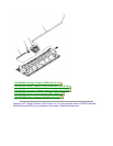
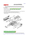
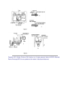
2. Use a needle nose pliers to release the claw of the tractor gear (1) and remove the gear.
3. Remove the change gear (2).
4. Raise the lock levers (3) on the left (4) and right (5) tractor assemblies.
5. Slide the lower tractor feed shaft (6) in the direction of arrow A and remove the shaft. This shaft is
square.
6. Slide the upper tractor feed shaft (7) in the direction of arrow A and remove the shaft. This shaft is
round.
7. Remove the left tractor assembly, the guide (8), and the right tractor assembly.
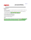
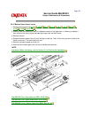
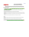
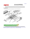
NOTE:
Installation
The tractors must be synchronized. Align the synchronization marks (9) in the same
direction.
Verify that the guide holes (10) in the tractor drive gears are facing the same direction.
The left tractor assembly must be positioned to the left (line feed motor side) of the plastic tab and
ground plate.
Lubrication
When lubricating, refer to Section 3.5 of this Service Handbook.