


Page: 159
Service Guide ML520/521
Chapter A Reference Charts
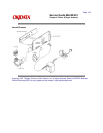
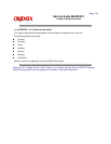
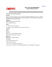
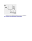
A.2.01 Main Controller Board (FJIM)
Function
The main controller board contains a microprocessor, EPROM, EEPROM, drive circuitry, 128 Kbyte
DRAM, sensors and interface connector. The AC voltages from the power supply are rectified and
regulated on the main controller board.
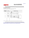
Firmware
05CB: CMOS Dynamic RAM (1 MBit)
05CA: EPROM (Program)
Fuses
F1: 125 Volt 2 amp. (AC line fuse)
F2: soldered - 2 amp. (protects the +40vdc motor drive circuit)
Jumpers
NONE
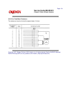
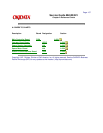
Sensors
SNS1: Rear / Top Feed Paper Out Sensor
SNS2: Bottom Feed Paper Out Sensor
Switches
BASW: Paper Path Select Switch
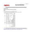
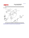
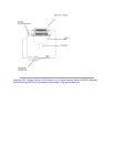
Test Points
Frame Ground CN1 pins 37,38
Logic Ground CN1 pin 33
+5 vdc : CN7 - Pin 6 (logic circuitry voltage)
+40 vdc: CN7 - Pins 29 and 31 (Printhead, Space Motor / Line Feed Motor Drive Voltage)