


Page: 146
Service Guide ML520/521
Chapter 4 Failure & Repair Analysis
4.8.04 Serial Interface Loopback Test
NOTE:
In order to run this test, the serial interface board must be installed with a serial loopback test connector
attached to it.
To perform the serial interface loopback test, follow these steps.
1. Place the printer in the Serial Diagnostic mode.
Set the Diagnostic Test menu item to YES.
2. Power off the printer.
3. Attach the loopback connector to the serial port.
4. Install continuous feed paper.
5. Power on the printer.
6. The message LOOP TEST prints.
7. The size of the Message Buffer prints.
8. One of the following three messages prints next.
If the message
OK
prints, the message buffer has been tested and no problems were found.
If the message
BAD
prints, there is a problem with the message buffer.
If the message
IF BAD
prints, the signal logic was tested and a problem was found.
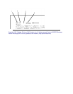
9. Hexadecimal characters 20 through 7F are transmitted through the transmit data line.
10. The receive data line receives the characters.
11. The message buffer stores the characters.
12. The data prints.
13. The test runs until the printer is powered off or the SELECT switch is pressed.
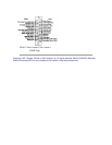
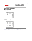
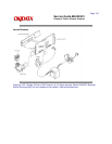
Loopback Connector Configuration
1. Jumper the following pins together.
Pin 2 to Pin 3
Pin 4 to Pin 5
Pin 8 to Pin 11
Pin 6 to Pin 20