


Page: 80
Service Guide ML520/521
Chapter 3 Maintenance & Disassembly
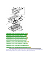
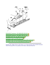
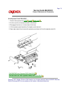
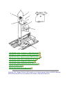
3.2.11 Space Motor and Roller Guide Assemblies
1. Perform these procedures:
3.2.01
, 3.2.02 , 3.2.04 , and 3.2.10 .
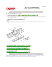
2. Remove the three screws (1).
3. Lift the space motor assembly (2).
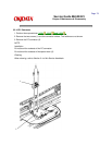
4. Remove the left (3) and right connector holders (4).
5. Remove the roller guide assembly (5) and guide roller spring (6).
6. Use firm pressure to pull the carriage cable (7) out to detach the cable from the space motor
assembly.
7. Remove the space motor assembly.
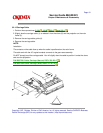
NOTE:
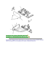
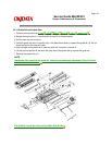
The guide roller assembly includes the guide roller (8), the guide roller holder (9), and the pin (10).
Installation: Position the guide roller assembly first.
The contact side of the cable faces down when the carriage cable is inserted into the connector on the
space motor assembly. Work the cable from side to side until it is fully seated in the connector. No
contacts should be visible.
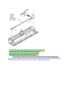
After installing the space motor assembly, check the printhead gap adjustment. Refer to Section
3.3 of this Service Handbook.
When lubricating, refer to Section 3.5 of this Service Handbook.