


Page: 101
Service Guide ML520/521
Chapter 3 Maintenance & Disassembly
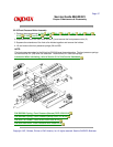
3.3.02 Printhead Gap Adjustment
General Information
Before performing this adjustment, always verify that the printhead is properly installed. This adjustment
should be performed when the following parts are replaced.
1. Printhead (3.2.02)
2. Space Motor Assembly (3.2.11)
3. Space Rack (3.2.13)
4. Guide Rail (3.2.15)
5. Platen Assembly (3.2.19)
6. Carriage Shaft (3.2.25)
NOTE:
Place a new ribbon cartridge in the printer before testing for parallelism.
If the density of the top portion of the characters differ from that of the bottom portion, follow steps 10 -
12.
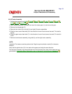
This adjustment is comprised of four phases.
1. Setup Phase
Steps 1-5
The cover is removed and the printhead is placed at a known reference point.
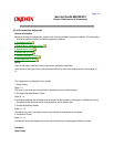
2. Printhead Gap Modification Phase
Steps 6 - 10
The distance between the printhead and the platen (at the left side of the platen) is modified by turning
the adjust screw which varies the vertical position of the space motor.
3. Parallel Adjustment Phase
Steps 11 - 12
The adjust cam lever is moved to ensure the printhead moves parallel to the platen.
4. Verification Phase
Steps 13 -14
Verifies that the parallel adjustment phase did not affect the printhead gap modification phase.
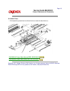
Procedure
Setup Phase