


113
Using Socket Services by Manipulating Dedicated Control Bits Section 6-7
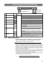
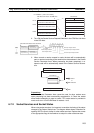
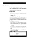
2. Turn ON the Socket Service Request Switches in the CPU Bus Unit Area
in the CIO Area.
3. When a send or receive request is made, the data will be automatically
sent or received according to the send/receive data address in the Socket
Service Parameter Area. When processing has been completed, a re-
sponse code will be automatically stored in the Socket Service Parame-
ters.
Precautions
A Socket Service Parameter Area cannot be used for other sockets once
open processing has been successfully completed for it. Check the socket
status before attempting to open a socket. TCP socket status is provided in
words m+9 to m+16 in the DM Area for sockets 1 to 8.
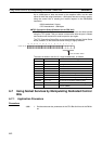
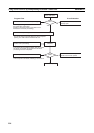
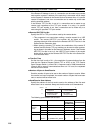
6-7-2 Socket Services and Socket Status
When using socket services, it is important to consider the timing of the status
changes in the Socket Status Area. The diagram below shows a flowchart for
opening UDP.The flow is similar for other socket services. Replace the names
of the appropriate flags in the flowchart to adapt it to other socket services.
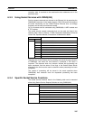
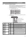
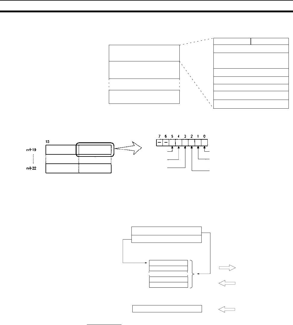
Remote UDP/TCP port No.
Number of bytes to send/receive
Send/Receive data address
Parameters
m = D30000 + (100 x unit number)
CPU Bus Unit Area in the DM Area
Socket Service Parameter Area 1
Socket Service Parameter Area 8
Socket Service Parameter Area 2
Time out time
Response code
UDP/TCP socket No.
Local UDP/TCP port No.
Remote IP address
15 0
m+18
m+28
m+88
Socket option
Socket Service
Request Switches 7
Socket Service
Request Switches 1
Socket Service
Request Switches 8
Socket Service
Request Switches 2
CPU Bus Unit Area in the CIO Area
Close Request
Switch
Receive Request Switch
Send Request Switch
UDP Open Request Switch
TCP Passive Open Request Switch
TCP Active Open Request Switch
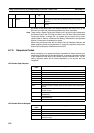
Number of bytes to send/receive
Send/receive data address
I/O memory
Send
or
Receive
Response code
Stored