


133
5. System settings
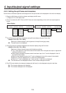
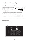
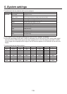
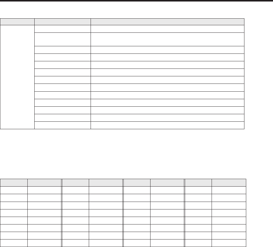
The table below lists the materials which can be assigned.
Button Signal Description
XP1 to 32 IN1 to IN16 SDI input 1 to 16
IN-A1, IN-A2,
IN-B1, IN-B2
Option slot
(SDI, Analog component, analog composite and DVI)
Black Internally generated signal, black
CBGD Internally generated signal, color background
CBAR Internally generated signal, color bar
FMEM1 to FMEM4 Frame memory image
CLN CLN (AUX only)
PVW PVW (AUX only)
PGM PGM (AUX only)
KeyOut KeyOut (AUX only)
MV1 MV1 (AUX only)
MV2 MV2 (AUX only)
NoAsign No assignment
The image will not be changed by pressing any button to which “NoAsign” is assigned.
If the multi view display output (MV1 or MV2) is selected as the AUX bus (AUX2, AUX3, AUX4) output signal
when the AUX2 to AUX4 output signals have been assigned for the multi view display output (MV1 or MV2),
a black image will be displayed as the image of the AUX bus that appears on the subscreen of the multi view
display.
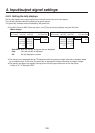
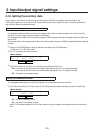
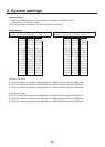
The table below lists the default settings.
Button Signal Button Signal Button Signal Button Signal
XP1 BLACK XP9 IN8 XP17 IN15 XP25 —
XP2 IN1 XP10 IN9 XP18 IN16 XP26 PGM
XP3 IN2 XP11 IN10 XP19 IN-A1 XP27 PVW
XP4 IN3 XP12 IN11 XP20 IN-A2 XP28 KeyOut
XP5 IN4 XP13 IN12 XP21 IN-B1 XP29 CLN
XP6 IN5 XP14 IN13 XP22 INB2 XP30 MV1
XP7 IN6 XP15 IN14 XP23 — XP31 MV2
XP8 IN7 XP16 Shift XP24 — XP32 Shift