


19
2. Functions in each area
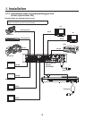
2-1. Control panel
123
456
789
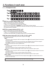
10 XPT DSBL EFF DSLV
WIPE
SQ1 SQ2
SL2SL1
3D1 3D2
PA GE
Z
MIX
WIPE
ON
1/17 2/18 3/19 4/20 5/21 6/22 7/23 8/24 9/25 10/26 11/27 12/28 13/29 14/30 15/31 16/32
PGM/A
AUX
PST/B
POWER
ALARM
F1 F2 F3 F4 F5
KEY PinP 1/2 DSK 1/2 AUX1 AUX2 AUX3 AUX4
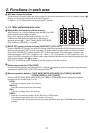
DSK1
ON
DSK2
ON
PinP1
ON
PinP2
ON
KEY
ON
FTB
ON
N/R R
BKGD KEY
MIX WIPE
CUT AUTOSHIFT
SHIFT
SHIFT
STOR
DEL
UNDO
BKGD
WIPE
MEM
RE
CALL
SHOT
MEM
PinP
MEM
CAM
MEM
BKGD
PAT T
KEY
PAT T
123
456
KEY
HOLD
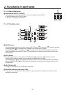
12
4
3
56
789
10 12
POSITIONER
MENU FUNCTION / AUX BUS DELEGATION MEMORY / PATTERNUSER
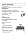
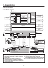
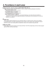
Multi-format
Live
Switcher
AV-HS450
11
CKEY
BKGD
PinP1
PinP2
DSK1
DSK2
TIME
CBGD
IMAGE A
IMAGE B
FMEM
SDCard
CTL
CAM
XPT
MV
IN
OUT
CONFIG
SYS
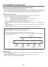
WIPE DIRECTION
AMBER:1 / GREEN :2
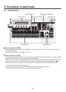
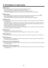
LCD menu area
User button area
SD memory card area Positioner area
Wipe pattern/memory area
Transition areaCrosspoint area
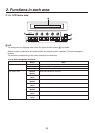
Power indicator [POWER]
This indicator lights when the power switch (
) on the rear panel is set to ON while power is supplied to the
DC power input socket.
It goes off when the power switch (
) is set to OFF.
Alarm indicator [ALARM]
This indicator lights when the mainframe’s cooling fan has stopped running or when there is a problem (voltage
drop) with the power supply of the mainframe or the control panel.
When this occurs, an alarm message is displayed on the LCD and on the OSD screen of the external monitor.
During the occurrence of an alarm, details of the trouble can be checked using the SYSTEM/Alarm menu.
Alarm information can be output to an external device from the control panel’s TALLY/GPI connector (
).
For details, refer to “5-8-2. Alarm message”.
If the alarm goes off, stop using the unit immediately and be sure to contact your dealer.
Continuing to use the unit even after the alarm goes off could damage it.