29
2. Functions in each area
2-1-8. Rear panel connections area
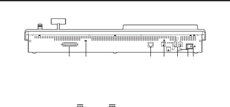
12V IN 1
TALLY / GPI MAINFRAME
OFFON
12V IN 2
POWER
SIGNAL
GND
LCD CONTRAST
SERVICE
NORMAL
TALLY/GPI input/output connector [TALLY/GPI] (D-sub 25-pin, female, inch screw)
For details on how to connect this connector, refer to “6. External interfaces”.
MAIN FRAME connector [MAIN FRAME] (RJ-45) (100 Base-TX)
Connect this to the mainframe using the supplied CAT5E cable (STP, straight, 10 m).
DC power input sockets [12V
IN1], [12V IN2] (DC 12 V, 0.8 A)
Connect the supplied AC adapters (for the control panel) to these sockets.
Ground connector [SIGNAL GND]
Connect to the system’s earth ground.
Power switch [POWER]
This is used to turn the power on and off.
SERVICE switch [NORMAL/SERVICE]
This switch is used for maintenance purposes.
For normal operations, select the “NORMAL” position.
LCD CONTRAST adjustment screw
This is used to adjust the contrast of the LCD display.


