


31
2. Functions in each area
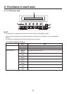
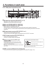
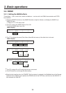
2-2-2. Rear panel connections area
IN1
IN2
SIGNAL
GND
REF
EDITOR
COM
TALLY/GPI
PANELLAN
234 56
321456789 10 11 12 13 14 15 16 C/C
U/C
1
SDI OUTPUTS
SDI INPUTS
DVI-D OUTPUTS
IN/OUT B2IN/OUT B1
SLOT B
IN/OUT A2IN/OUT A1
SLOT A
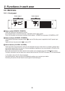
SDI signal input connectors [SDI INPUTS 1 to 16]
9 to 16: The color collector function can be used.
13 to 16: The up-converter function can be used.
Option slot [SLOTA] (IN/OUT A1, IN/OUT A2)
Option slot [SLOTB] (IN/OUT B1, IN/OUT B2)
Each of these is an input/output option slot.
A DVI input board, analog output board or other option board can be installed in these slots.
For details, refer to “1-3. How to install the option boards” and the operating instructions of the board
concerned.
SDI signal output connectors [SDI OUTPUTS 1 to 4]
1 to 4: These can be allocated by the menus.
Two sets of the same output signals are distributed from the OUTPUT1 connector.
DVI-D output connectors [DVI-D OUTPUTS 5, 6]
These can be allocated by the menus.
The DVI-I connector cable cannot be used.
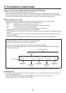
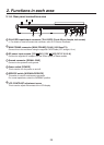
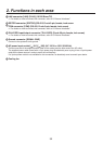
Reference input connector/BB output
connector [REF]
Loop-through output in the external sync mode.
If the loop-through output is not going to be used,
provide a 75-ohm termination.
BB signals output from both connectors in the internal
sync mode.
<In the external synchronization mode>
External synchronization signal input
Loop-through output
Input the external synchronization signal to the upper of
the two connectors shown above.
REF
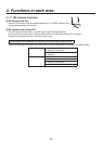
PANEL connector [PANEL] (RJ-45) (100 Base-TX)
Connect this to the control panel using the supplied CAT5E cable (STP, straight, 10 m).