157
6. External interfaces
6-3. Control panel
6-3-1. TALLY/GPI
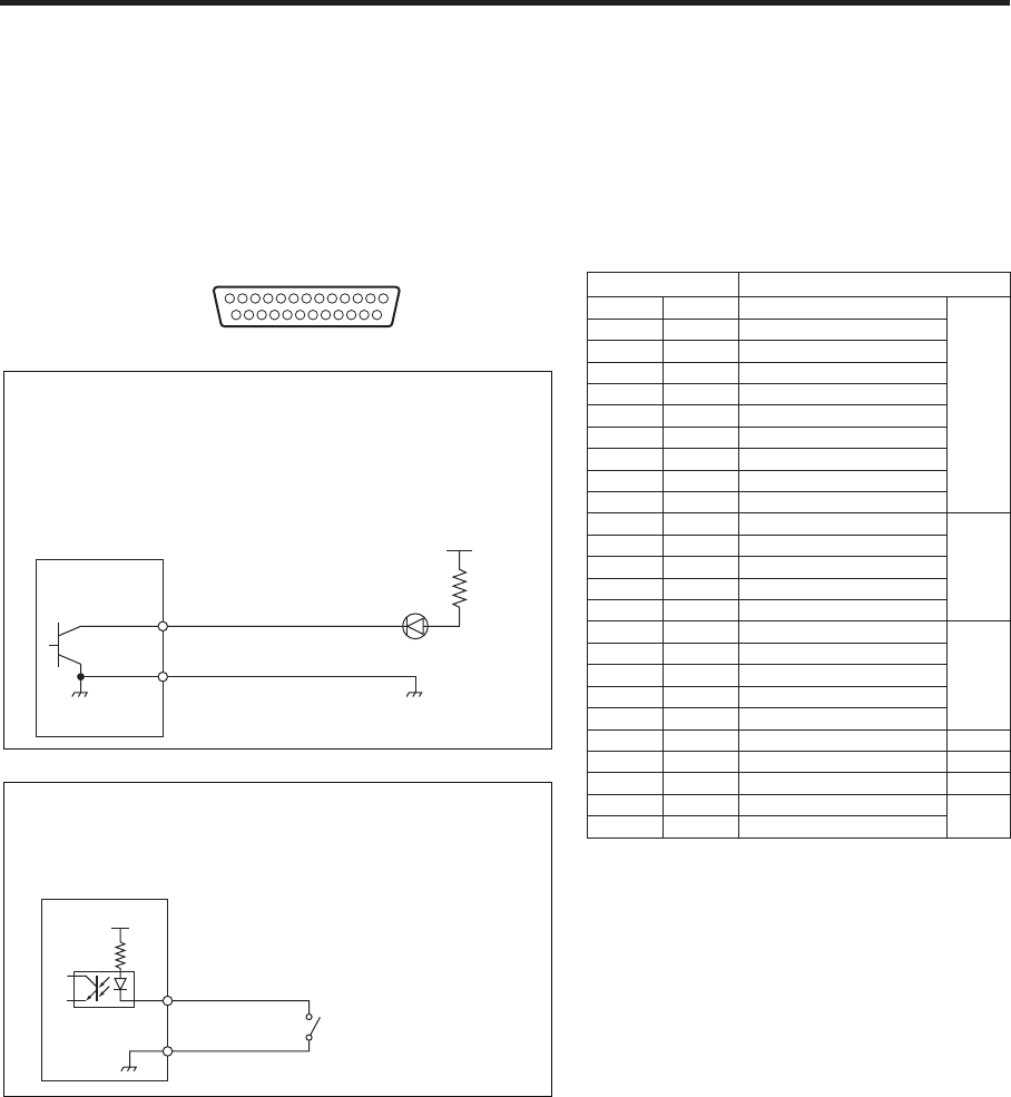
This connector is provided with eight contact input ports (GPI In) for controlling the unit from an external device,
8 ports (GPI Out) for outputting the tally and status information from the unit to the external device, and one port
(ALARM Out) that is used exclusively as the alarm output.
For details of the settings, refer to “5-7-3. Setting the GPI”.
13
1
25
14
Com
GPI Out
ALARM Out
Example of GPI Out and ALARM connections
Ensure that the conditions given below are satisfied.
Dielectric strength: Max. DC 24 V
Current: Max. 50 mA
AV-HS450N
(Max. voltage: 24 V)
Tally LED
(Max. current: 50 mA)
Com
GPI In
+3.3 V
Example of GPI In connections
Provide contact inputs.
AV-HS450N
D-sub 25-pin, female, inch screw
Pin No. Signal name
1 GPI In Com
IN
14 GPI In Com
2 GPI In 1
15 GPI In 2
3 GPI In 3
16 GPI In 4
4 GPI In 5
17 GPI In 6
5 GPI In 7
18 GPI In 8
6 GPI Out Com
A
19 GPI Out 1
7 GPI Out 2
20 GPI Out 3
8 GPI Out 4
21 GPI Out Com
B
9 GPI Out 5
22 GPI Out 6
10 GPI Out 7
23 GPI Out 8
11 DC 5 V
24 DC 5 V
12 NC
25 ALARM Com
13 ALARM Out


