ENGLISH
– 15
Getting Started
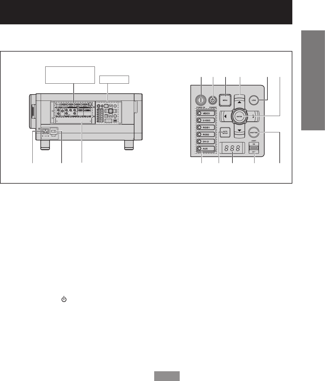
Controls
Side
1
AC IN terminal (p. 35)
Connect the supplied line power cord into this
receptacle.
Do not connect any other cable to this socket.
2
MAIN POWER switch (pp. 35-37)
Use this switch to turn on “I” and off “○” the
commercial line power applied to the projector.
3
Slot cover (p. 29)
Install the input module here.
4
POWER ON ( I ) button (pp. 35, 36)
When the projector is in standby mode with the
MAIN POWER switch of the projector at the
“ l ” side, this button switches the projector to
projection mode.
5
POWER STANDBY ( ) button (pp. 35, 37)
When the projector is in projection mode with the
MAIN POWER switch of the projector at the “ l ”
side, this button switches the projector to standby
mode.
6
MENU button (pp. 49, 51)
Use this button to return to the previous screen
when the sub menu is displayed. If you hold it
down for at least 3 seconds while the on-screen
indication is OFF, the OFF state is cancelled.
7
Arrow ▲▼◄► buttons (pp. 51, 86)
Use to select an item on the menu screen, change
setting and adjust the level.
Also use them to enter the “SECURITY” password.
8
LENS button (p. 38)
Switches to the adjustment mode for lens focus,
zoom and shift (position).
9
ENTER button (p. 51)
Press this button to enter your menu selection or
to run function.
j
Input select (VIDEO, S-VIDEO, RGB1, RGB2,
DVI-D, AUX) button (p. 46)
Use to change the VIDEO, S-VIDEO, RGB1,
RGB2, DVI-D and AUX (optional input module)
input ports.
k
AUTO SETUP button (p. 47)
Pressing this button while projecting an image
automatically corrects the picture positioning
on the screen. While the auto setup feature is
active, a message “PROGRESS...” appears on the
screen.
l
Self-diagnosis display (pp. 116-117)
m
LIGHT ON/OFF button
This switch is used for illuminating the connection
terminals and controls.
n
SHUTTER button (p. 46)
Press this button to black out the image
temporarily.
Note
The AUX button to switch the input is disabled •
when an optional input module is not connected.
Connection
terminals (p. 16)
Controls
123
4
j
5
k
6
l
7
m
8
n
9


