32 –
ENGLISH
Installation of input module (optional) (continued)
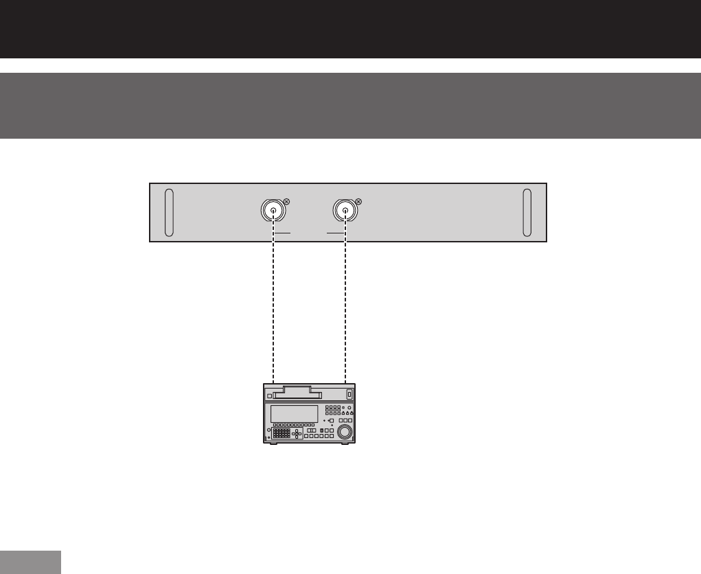
Connecting the signal to the dual link HD/SD-SDI input
module
Dual Link
HD-SDI
Module
ET-MD100SD4
LINK-A
SERIAL IN
LINK-B
Dual link HD/SD-SDI input module (optional)
ET-MD100SD4
HD-SDI or
SD-SDI signal
Business digital
VCR
When connecting a single link signal, connect to the LINK-A terminal.•
When connecting a dual link signal, connect to both the LINK-A and LINK-B terminals.•
Note
You can switch the input format mode from the SYSTEM SELECTOR menu. (pp. 56-57)•
Settings specific to the connected device are required. (pp. 72-73)•
To send the pictures properly, use a connecting cable with the specifications of 5CFB or higher (5CFB, 7CFB, •
etc.) or of Belden1694A or higher. Also, use a cable that is shorter than 100 m.
Make sure that the cables used to link LINK-A terminal and LINK-B terminal are of the same type and length. •
If there is a difference in length greater than 4 m between the two cables, the images will not be projected
correctly.
When connecting to dual link signals, connect directly to the signal output device without connecting through a •
distributor or other such device. A phase difference may occur between the LINK-A signal and LINK-B signal,
which may prevent the image from being correctly projected.
If the connected signal is unstable, the automatic distinction function may not operate correctly. In this case, •
switch to a mode that better suits the signal format from the SYSTEM SELECTOR menu.


