


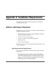
Appendix A. Installation Requirements
1900-A2-GN20-00 BitStorm 1900 Installation and Maintenance Guide A-109
1
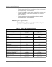
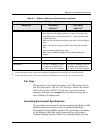
10306 configuration assumes a full chassis consisting of a 260 Watt AC Power Card, MIU and 10-10306 CO Cards.
2
10224 configuration assumes a full chassis consisting of a 260 Watt AC Power Card, MIU and 10-10224 CO Cards.
Fan Trays
The fan shelf provides forced-air cooling in the 7RU modem chassis
and 3RU filter chassis. The -48 V DC fan tray is ideal for the Central
Office (CO) and the 110/220 V AC fan tray is geared toward the
enterprise. Fan shelves are required for any chassis housing one or
more 10 Mbps CO modem cards.
Grounding Environment Specifications
The grounding environnment for the bay containing the BitStorm 1900
shelf must meet local electrical codes and Integrated Building
Distribution Network (IBDN) standards. The grounding environment
for the BitStorm 1900 shelf and its supporting bay can be either a
Common Bonding Network (CBN) or an Isolated Bonding Network
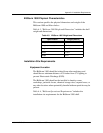
Connectors • 2 Rows of Omni-Grid Connectors for Data Out
• Rear Top Row- Left to Right: Cards 10-1, Lines 1-12 on each card
• Rear Bottom Row- Left to Right: Cards 10-1, Lines 13-24 each card
(10224 Cards Only)
• Rear Top Two right most connecotrs are not used in current configura-
tions.
• Mate-n-Lock Power Connector for DC Power Cards (Not used with
AC)
• Alarm Connector (Not Currently Used)
• WAN Interface (WAN Card Specific- See Individual WAN Card
Details)
Dependencies Air Baffle, Fan Tray Air Baffle, Fan Tray
Cable List See Individual Cards See Individual Cards
Certifications FCC Part 15, Subpart B, Class A,
UL 60950, cUL, NEBS Level 3,
CE, TNV-3, ETSI ETS 300 386-2
FCC Part 15, Subpart B, Class A,
UL 60950, cUL, NEBS Level 3,
CE, TNV-3, ETSI ETS 300 386-2
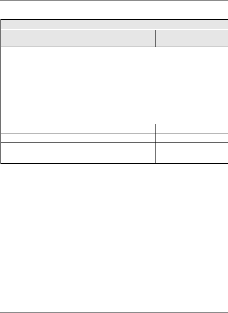
Table A-1: BitStorm 1900 System Specifications (continued)
BitStorm 1900 System Specifications
Description Front Mount
10306
Full
1
Front Mount
10224 Full
2