


2. BitStorm 1900 Installation and Testing
2-52 BitStorm 1900 Installation and Maintenance Guide 1900-A2-GN20-00
Step Procedure (continued)
NOTE: The redundant power supply sources connect to two pairs of wires on
the BitStorm 1900’s power harness and are electrically the same.
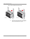
5.) Route the other end of the DC power harness to the DC power
connector on the backplane of the BitStorm 1900 modem shelf.
The connector only fits one way.
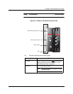
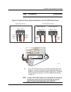
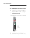
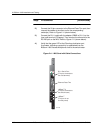
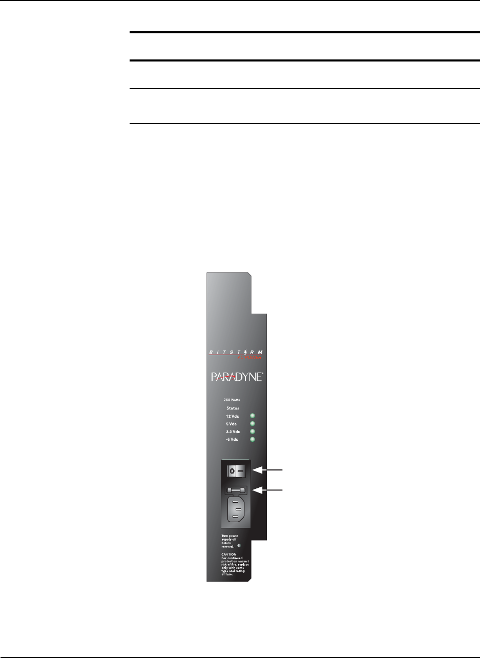
6.) For an AC power supply, connect the power cord to the IEC
terminal connection on the front panel.
Figure 2-9: Typical Power Connection to 260W AC Power Source
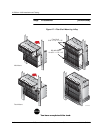
7.) Route the other end of the cord to a grounded socket.
8.) Re-seat the power, modem, and MIU Shelf processor into their
shelf backplane connectors.
ON/OFF
FUSE
3A, 250V AC
02-17181