


Appendix B. Cabling Specifications
B-130 BitStorm 1900 Installation and Maintenance Guide 1900-A2-GN20-00
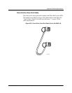
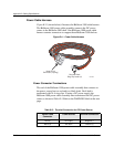
Power Cable Harness
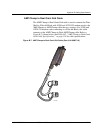
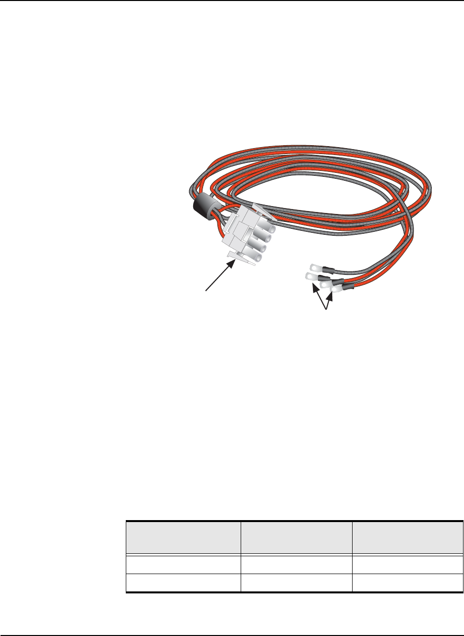
Figure B-11 (shown below) illustrates the BitStorm 1900 cable harness.
The BitStorm 1900 power cable assembly connects the DC power
source to the BitStorm 1900 shelf. One BitStorm 1900 power cable
harness contains connectors to support three BitStorm 1900 shelves.
Figure B-11: Power Cable Harness
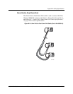
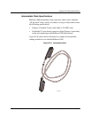
Power Connector Terminations
The end of the BitStorm 1900 power cable assembly that connects to
the power source has two red and two black leads. Each lead is
terminated with 24-4 ring clips. If using a DC power supply, the
BitStorm 1900 power cable assembly must terminate at the DC power
source as shown in Table B-5. Refer to the WARNING label on the next
page.
Mate-N-Lok
Connector (4-prong)
Red and Black
Ring Clip Leads (4)
02-17206
Table B-5: Terminal Connection for DC Power Source
Power Cable
Connector
Power Source Terminal Connection
Red (2) DC supply Negative (-)
Black (2) DC return Positive (+)