


2. BitStorm 1900 Installation and Testing
2-56 BitStorm 1900 Installation and Maintenance Guide 1900-A2-GN20-00
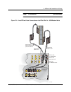
Step Procedure (continued)
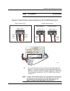
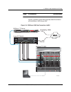
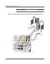
2.) Connect the 50-pin connector to the Ethernet Pass-Thru port, then
connect the cables at the other end to the corresponding
switch(es). Refer to Figure 2-11 (shown below).
3.) Connect the RJ-11 cable with the adapter (DB9S to RJ-11) to the
local craft terminal (PC/laptop). Then connect the other end to the
RS-232 port on the MIU. Refer to Figure 2-11 (shown below).
4.) Verify that the green LED at the EtherLoop hub/router port
illuminates, indicating connectivity is established from the
BitStorm 1900 Access Multiplexer shelf to the switch/router.
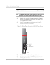
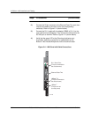
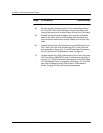
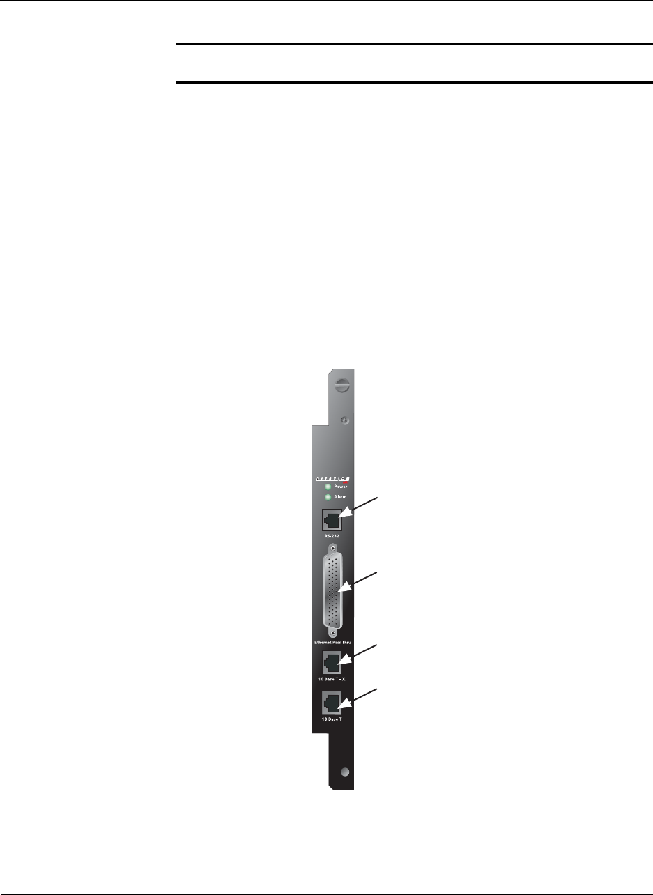
Figure 2-11: MIU Card with Cable Connections
RJ11 Serial Port
(This port connects to
the craft terminal)
Ethernet Pass-Thru
10Base T-X
(This port connects to
the switch/router)
10Base T
(This port is not
currently used)
02-17183