


Operation
3-8
3160-A2-GB21-80
March 1999
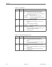
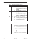
Table 3-3. DTE Drop/Insert (DSX-1) Interface LEDs (2 of 2)
Name MeaningColor
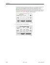
ALRM Yellow Indicates whether an alarm condition exists on the received DTE
Drop/Insert (DSX-1) signal.
ON:
An alarm condition (LOS, LOF, EER, Yellow, AIS) exists
on the received DTE Drop/Insert (DSX-1) signal. Use
the Device Health and Status command to determine
the alarm type.
OFF:
No alarm condition exists on the DTE Drop/Insert
(DSX-1) interface signal.
PDV Yellow Monitors Pulse Density Violations (PDV) on the received DTE
Drop/Insert (DSX-1) signal.
ON
: At least one PDV was detected (and corrected) on the
received DTE Drop/Insert (DSX-1) signal during the
sampling period.
OFF:
No PDVs were detected on the received DTE
Drop/Insert (DSX-1) signal during the sampling period.
BPV Yellow Monitors Bipolar Violations (BPV) on the received DTE
Drop/Insert (DSX-1) signal.
ON:
At least one BPV was detected (and corrected) on the
received DTE Drop/Insert (DSX-1) signal during the
sampling period.
OFF:
No BPVs were detected on the received DTE
Drop/Insert (DSX-1) signal during the sampling period.
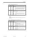
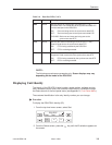
Table 3-4. Data Port LEDs (1 of 2)
Name Color Meaning
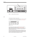
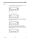
DTR Green Monitors the state of interchange circuit CD (CCITT 108/1, /2) –
Data Terminal Ready received from the synchronous data DTE.
ON:
DTR is being asserted by the synchronous data DTE.
OFF:
DTR is not being asserted.
TXD Yellow Monitors activity on interchange circuit BA (CCITT 103) –
Transmitted Data. This is the data sent from the synchronous
data DTE to the data port on the DSU/CSU.
ON:
Ones are being received from the synchronous data
DTE.
OFF:
Zeros are being received from the synchronous data
DTE.
CYCLING:
Both ones and zeros are being received from the
synchronous data DTE.