


Operation
3-29
3160-A2-GB21-80
March 1999
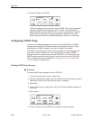
Configuring DS0 Channels
The DSU/CSU provides channel configuration options that allow you to do the
following:
H Display the DS0 assignments for the network, DTE Drop/Insert (DSX-1), and
data port interfaces.
H Allocate DS0 channels on the DTE Drop/Insert (DSX-1) interface to the
network interface.
H Allocate DS0 channels on the network or DTE Drop/Insert (DSX-1) interface
to particular data ports.
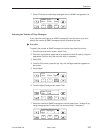
H Clear (deallocate) all DS0 channels from the network, DTE Drop/Insert
(DSX-1), or data port interface.
H Map data from one port to another.
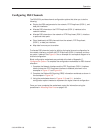
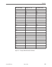
To allocate DS0 channels, begin by defining the logical channel configuration for
the network interface, and then the DTE Drop/Insert (DSX-1) interface, and then
any ports, if desired. See Figure 3-6 for an example of a conceptual diagram of a
channel configuration.
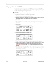
Blank configuration worksheets are provided at the back of Appendix C,
Configuration Options
. To complete the configuration worksheets for DS0 channel
allocation:
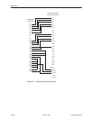
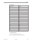
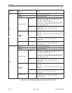
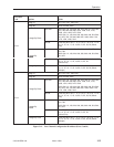
1. Complete the Network Interface and the DTE Drop/Insert (DSX-1) Interface
tables (unless the DTE Drop/Insert interface is disabled) as shown in the
examples in Figure 3-7 and Figure 3-8.
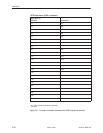
2. Complete the Robbed Bit Signaling (RBS) information worksheet as shown in
the examples in Figure 3-9.
3. Using the worksheets shown in Figures 3-10 and 3-11, circle the
configuration options needed to implement the logical channel configuration.
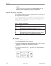
Once you have completed the worksheets, enter this information using the
procedures in
Allocating Data Ports
on page 3-38.