52 C1553M-B (4/05)
b. Local Port: The local port is the port the Pelco PTZ device driver uses to transmit commands. If your system is secured behind a
firewall, enter one of the ports made available by the firewall. Otherwise, enter 0 to have the driver randomly assign an available port.
Tip: To find out what port the driver assigned, switch or control the device in the VMX300(-E) client, and then use the netstat command
at the DOS prompt to view assigned ports.
c. Remote IP, Remote Port, Protocol: The remote device is the device the Pelco PTZ camera is physically connected to. If the camera is
connected to a PelcoNet device, follow the instructions in step (1). If the camera is connected to some other kind of device, follow the
instructions in step (2).
(1) PelcoNet: Select the PelcoNet protocol from the Protocol drop-down box. If the PelcoNet device has a user name and password
defined in the device settings, you will be prompted to enter the user name and password before proceeding. Enter the IP
address of the PelcoNet device in the Remote IP box. In the Remote Port box, select the port on the PelcoNet device that the
camera is connected to. Select 1 if the camera is connected to COM 1 on the PelcoNet device. Select 2 if the camera is
connected to COM 2. This port must be exposed in the PelcoNet device properties configuration. For more information on
configuring PelcoNet device properties, refer to the Add a PelcoNet MPEG Device section.
(2) Other: Select the desired transport protocol from the Protocol drop-down box. The remote IP is the IP address of the VMX300(-E)
workstation the remote device’s driver runs on. Enter the remote IP in the Remote IP box. In the Remote Port box, enter the port
the remote device’s driver uses to receive commands.
d. Refer to Step 3 for instructions on completing the fields in the Miscellaneous section.
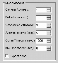
3. Miscellaneous: Configure the following fields in the Miscellaneous section of the Communications tab:
Figure 45. Miscellaneous Section of Communications Tab
Camera Address: Enter the camera address. The address must match the address specified by the camera DIP switch settings.
Poll Interval (sec): Applies to the Spectra III (D Protocol) only. The poll interval specifies how often the device driver attempts to query the
camera for feedback on its position. This determines how often the positions of device icons in the client are updated.
Feedback queries are suspended when the camera is being controlled. The optimal value of 1 is recommended.
Idle Disconnect (sec): (Optional) Enter the number of seconds of inactivity you want to elapse before VMX300(-E) closes the COM port (direct
serial connection) or the local port (IP connection). The port will open again automatically when a new command is sent
to the camera. Use the default value of 0 to indicate that the port should never be closed while the driver is running.
Note that the following fields should not be changed:
Connection Attempts: This field is used for troubleshooting and should specify the default value of 3.
Attempt Interval (sec): This field is used for troubleshooting and should specify the default value of 5.
Comm Timeout (msec): This field is used for troubleshooting and should specify the default value of 1000.
Expect echo: This field is reserved for future development.


