C1553M-B (4/05) 83
CONFIGURE THE I/O TAB
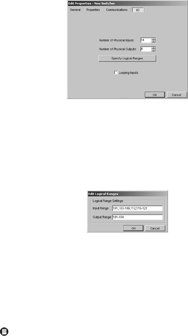
Figure 92. I/O Tab for ASCII Switcher
Use the I/O tab to specify how many physical inputs and outputs are available for switching cameras and to specify logical number ranges.
1. Enter the number of physical inputs available for switching cameras. To prevent VMX300(-E) from using some of the switcher’s physical
inputs, exclude them from the count of available inputs. For example, if the switcher has a total of 16 physical inputs, 14 of which you want
available for switching cameras, enter 14 in this field.
2. Enter the number of physical outputs available for switching cameras. If some of the switcher’s outputs are partitioned for dedicated use by
another type of device, such as a joystick, exclude them from the count of available outputs. For example, if the switcher has eight physical
outputs in total, two of which are going to be used by other devices, enter 6 in this field.
3. Optional: To specify the logical numbering scheme, click Specify Logical Ranges. The Edit Logical Ranges dialog box appears.
Figure 93. Edit Logical Ranges Dialog Box
By default, VMX300(-E) assigns sequential identifiers to the available inputs and outputs. Inputs are named Input1, Input2, ... Inputi, where
i is the total number of physical inputs available for switching cameras. Outputs are named Output1, Output2, ... Outputi, where i is the total
number of physical outputs available for switching cameras. Looping inputs are named LoopingInput1, LoopingInput2, ... LoopingInputi,
where i is the total number of physical inputs available for switching cameras.
a. Enter the numbers you want to use to identify inputs in the Input Range box.
b. Enter the numbers you want to use to identify outputs in the Output Range box. You can list numbers and/or specify ranges.
Example, 101,103-109,112,115-121 is a valid input range for a switcher with 16 available inputs. In this case, physical Input1 will be named
Input101 in VMX300(-E), physical Input2 will be named Input103, physical Input3 will be named Input 104, and so on. If looping input is
enabled for the switcher, the LoopingInputs will be named LoopingInput101, LoopingInput103, LoopingInput104, and so on.
4. To enable looping inputs on a switcher that supports it, click Looping Inputs. Looping inputs on a switcher allow the switcher to function as
a source device when defining connections. Refer to the ASCII Connections section for more information.
NOTE: If you assigned logical numbers to the inputs and/or outputs when you configured the switcher through the management system
provided with the switcher, you must assign the same logical numbers in VMX300(-E). For information on accessing the management
system functions, refer to the appropriate switcher installation/operation manual.


