


Installation and Initialization AP-4000 Series User Guide
AP-4000 Series Hardware Description
21
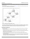
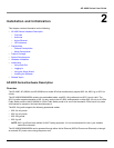
• The Active Ethernet (AE) integrated module receives ~48 VDC over a standard Category 5 Ethernet cable.
• To use Active Ethernet, you must have an AE hub (also known as a power injector) connected to the network.
• The cable length between the AE hub and the Access Point should not exceed 100 meters (approximately 325 feet).
The AE hub is not a repeater and does not amplify the Ethernet data signal.
• If connected to an AE hub and an AC power simultaneously, the Access Point draws power from Active Ethernet.
Also see Hardware Specifications.
NOTE: The AP’s 802.3af-compliant Active Ethernet module is backwards compatible with all ORiNOCO Active Ethernet
hubs that do not support the IEEE 802.3af standard.
LED Indicators
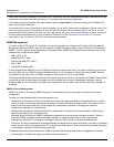
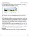
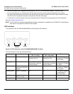
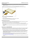
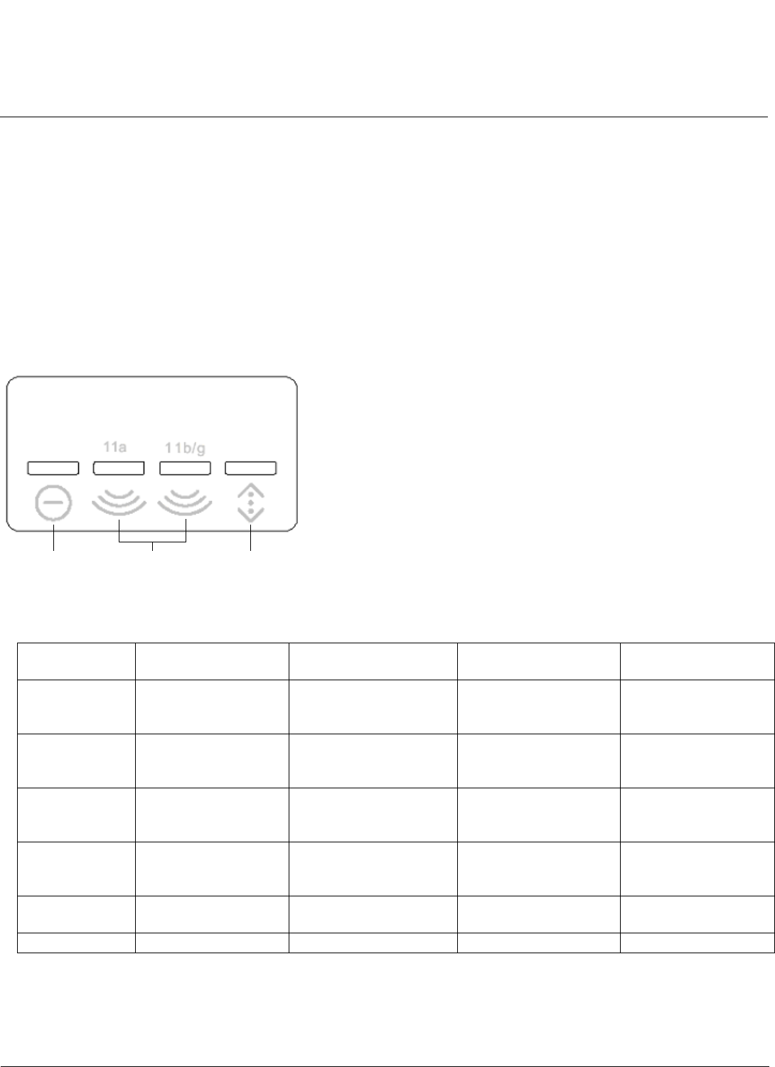
The top panel of the AP-4000/4000M/4900M has the following LED indicators.
Figure 2-3 LED Indicators on the AP-4000/4000M/4900M Top Panel
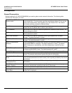
The LED indicators exhibit the following behavior:
Indication Power Wireless Interface A
(802.11a radio)
Wireless Interface B
(802.11b/g radio)
Ethernet
Solid Green AP image running. Wireless interface A is
preparing for use.
Wireless interface B is
preparing for use.
Ethernet interface is
connected at 100 Mbps
with no traffic.
Blinking Green n/a Wireless interface A is
transmitting or receiving
wireless packets.
Wireless interface B is
transmitting or receiving
wireless packets.
Ethernet interface is
connected at 100 Mbps
with traffic.
Solid Amber The Bootloader is
loading the application
software.
n/a n/a Ethernet interface is
connected at 10 Mbps
with no traffic.
Blinking Amber The AP is reloading. n/a n/a The Ethernet interface
is connected at 10
Mbps with traffic.
Solid Red Power On Self Test
(POST) running.
n/a n/a n/a
Blinking Red Rebooting. n/a n/a n/a
Power Wireless
Interfaces
Ethernet