


2 – General Description
Chassis Controls and LEDs
2-2 59021-05 A
2.1
Chassis Controls and LEDs
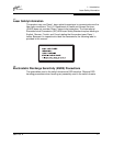
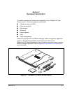
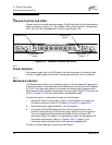
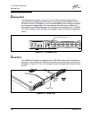
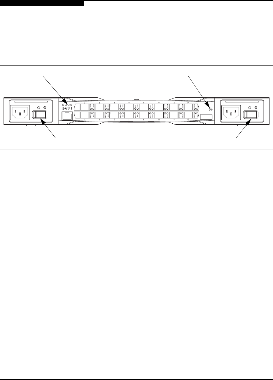
Chassis controls include the power supply On/Off switches and the Maintenance
button as shown in Figure 2-2. The chassis LEDs include the Over Temperature
LED, Fan Fail LED, Heartbeat LED, and the Input Power LED.
Figure 2-2. Chassis Controls and LEDS
2.1.1
Power Switches
Each power supply has an On/Off switch that controls power to the switch logic
circuitry. To apply power to the switch, place both switches in the On position.
2.1.2
Maintenance Button
The Maintenance button is a momentary switch on the front panel. Its purpose is
to place the switch in maintenance mode. Maintenance mode sets the IP address
to 10.0.0.1 and provides access to the switch for maintenance purposes when
flash memory or the resident configuration file is corrupted. Refer to ”Recovering a
Switch” on page 5-12 for information about maintenance mode.
To place the switch in maintenance mode, do the following:
1. Isolate the switch from the fabric. Open a Telnet session, and enter the
Shutdown command. Refer to ”Shutdown Command” on page B-65.
2. Place both power supply switches in the Off position.
3. Press and hold the Maintenance button with a pointed tool for a few
seconds, then place one of the power supply switches in the On position.
You can release the Maintenance button after the Input Power LED
illuminates. When the switch is in maintenance mode, the Heartbeat LED
illuminates continuously. Refer to ”Chassis LEDs” on page 2-3 for
information about the Input Power LED and the Heartbeat LED.
To return to normal operation, power cycle the switch.
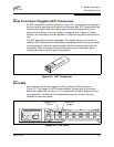
Chassis LEDs
Left Power
Switch
Right Power
Switch
Maintenance
Button