


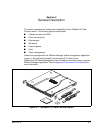

2 – General Description
Power Supplies
59021-05 A 2-9
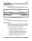
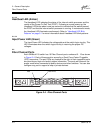
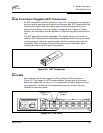
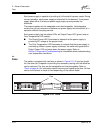
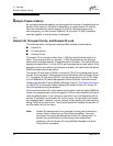
The serial port connector requires a null-modem F/F DB9 cable. The pins on the
switch RS-232 connector are shown in Figure 2-8 and identified in Table 2-1.
Refer to ”Connect the Management Workstation to the Switch” on page 4-8 for
information about connecting the management workstation through the serial port.
2.5
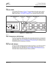
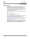
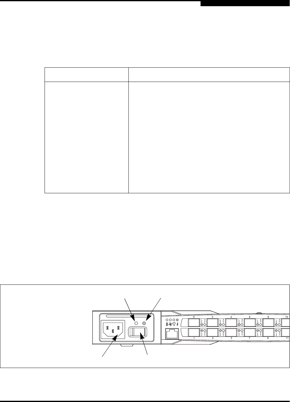
Power Supplies
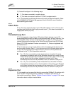
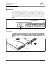
The power supplies convert standard 110 or 230 VAC to DC voltages for the
various switch circuits. Each power supply has an AC power receptacle, an On/Off
switch, and two status LEDs as shown in Figure 2-9. After connecting a power
supply to an AC voltage source and placing the power switch in the On position,
the power supply is energized and DC voltage is delivered to the switch logic
circuitry. Refer to Section 6 Removal/Replacement for information about replacing
a power supply.
Figure 2-9. Power Supply Components
Table 2-1. Serial Port Pin Identification
Pin Number Description
1 Carrier Detect (DCD)
2 Receive Data (RxD)
3 Transmit Data (TxD)
4 Data Terminal Ready (DTR)
5 Signal Ground (GND)
6 Data Set Ready (DSR)
7 Request to Send (RTS)
8 Clear to Send (CTS)
9 Ring Indicator (RI)
AC Power
Receptacle
Output Power LED
(Green)
Over Temperature LED
(Amber)
On/Off Switch