


4 – Installation
Installing a Switch
59021-05 A 4-7
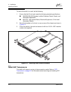
4. Confirm that the Output Power LEDs on both power supplies are illuminated.
If not, do the following:
a. Check voltage at the AC power source.
b. Inspect the power cord.
c. Replace the power supply.
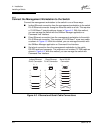
5. Observe the Heartbeat LED to determine the results of the Power On Self
Test (POST). The POST tests the condition of firmware, memories,
data-paths, and switch logic circuitry and passes a blink code to the
Heartbeat LED. If the Heartbeat LED blinks steadily about once per second,
the POST was successful, and you can continue with the installation
process. Any other blink pattern appears indicates that an error has
occurred. Refer to ”Heartbeat LED Blink Patterns” on page 5-1 for more
information about the error blink pattern.