


59021-05 A 5-1
Section 5
Diagnostics/Troubleshooting
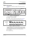
Diagnostic information about the switch is available through the chassis LEDs, the
power supply LEDs, and the port LEDs. Diagnostic information is also available
through the SANbox Manager and CLI event logs and error displays. This section
describes two types of diagnostics: Power On Self Test (POST) and chassis.
POST diagnostics describe the Heartbeat LED and the port Logged-In LED
indications. Chassis diagnostics cover power supply and fan diagnostics as well
as over temperature conditions. This section also describes how to use
maintenance mode to recover a disabled switch.
5.1
POST Diagnostics
The switch performs a series of Power On Self Tests (POST) as part of its
power-up procedure. The POST diagnostic program performs the following tests:
■ Checksum tests on the boot firmware in PROM and the switch firmware in
flash memory
■ Internal data loopback test on all ports
■ Access and integrity test on the ASIC
During the POST, the switch logs any errors encountered. Some POST errors are
fatal, others are non-fatal. The switch uses the Heartbeat LED and the Logged-In
LED to indicate switch and port status. A fatal error disables the switch so that it
will not operate. A non-fatal error allows the switch to operate, but disables the
ports that have errors. Whether the problem is fatal or non-fatal, contact your
authorized maintenance provider.
If there are no errors, the Heartbeat LED blinks at a steady rate of once per
second. If a fatal error occurs, the Heartbeat LED will show an error blink pattern.
If there are non-fatal errors, the switch disables the failed ports and flashes the
associated Logged-In LEDs. Refer to ”Heartbeat LED Blink Patterns” on page 5-1
for more information about Heartbeat LED blink patterns.
5.1.1
Heartbeat LED Blink Patterns
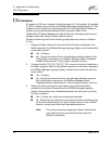
5.1.1.1
Normal (all pass)
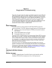
If all POST diagnostics pass, the switch will go to normal operation and the
Heartbeat LED will blink at a steady rate of one (1) blink per second.