


FIGURES iii
Figures
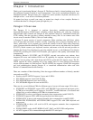
Figure 1 Paragon II Main Units ....................................................................................................................2
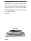
Figure 2 P2-UMT832, P2-UST, and P2CIM-PS2.........................................................................................2
Figure 3 P2-EUST........................................................................................................................................3
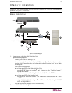
Figure 4 Installation Diagram.......................................................................................................................5
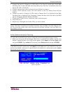
Figure 5 Login Menu....................................................................................................................................6
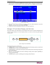
Figure 6 Selection Menu..............................................................................................................................7
Figure 7 Paragon II Front Panel Buttons......................................................................................................7
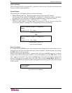
Figure 8 LCD Normal Display ......................................................................................................................8
Figure 9 Power Up Clear Database.............................................................................................................8
Figure 10 LCD Functions.............................................................................................................................9
Figure 11 Function Selection .......................................................................................................................9
Figure 12 Display Ver. and SN.....................................................................................................................9
Figure 13 User Station Test.........................................................................................................................9
Figure 14 Channel CIM (UKVM) Test .......................................................................................................10
Figure 15 Stacking Support........................................................................................................................10
Figure 16 Set LCD Contrast.......................................................................................................................10
Figure 17 Auto Configure...........................................................................................................................10
Figure 18 Format of OSUI screens ............................................................................................................12
Figure 19 Login Menu for a Paragon II ......................................................................................................14
Figure 20 Selection Menu..........................................................................................................................15
Figure 21 Administration Menu..................................................................................................................16
Figure 22 Channel Configuration Menu of a P2-UMT832M .......................................................................16
Figure 23 Sample cascaded system..........................................................................................................17
Figure 24 Selection Menu..........................................................................................................................18
Figure 25 Administration Menu..................................................................................................................19
Figure 26 Channel Configuration Menu for a P2-UMT832M......................................................................19
Figure 27 Paragon HubPac........................................................................................................................22
Figure 28 Connecting a P2-UMT832M to a HubPac..................................................................................23
Figure 29 Login Menu................................................................................................................................25
Figure 30 Selection Menu for a P2-UMT832M...........................................................................................26
Figure 31 Manual Video Gain/Skew Delay Adjustment Display for P2-EUST............................................27
Figure 32 Manual Video Gain Adjustment for P2-UST...............................................................................28
Figure 33 Selection Menu in order by Channel Port Number..................................................................... 29
Figure 34 Selection Menu in order by Port Name......................................................................................29
Figure 35 User Profile Menu......................................................................................................................33
Figure 36 Directional Prompts in Message Bar..........................................................................................33
Figure 37 Prompt in Message Bar to Save Changes.................................................................................35
Figure 38 Help Menu .................................................................................................................................35
Figure 39 Information Menu.......................................................................................................................37
Figure 40 Administration Menu..................................................................................................................39
Figure 41 System Configuration Menu for P2-EUST .................................................................................40
Figure 42 Force Switch Message...............................................................................................................42
Figure 43 Left panel of the User Configuration Menu ................................................................................43
Figure 44 Right panel of the User Configuration Menu..............................................................................44
Figure 45 Left panel of the Channel Configuration Menu...........................................................................45
Figure 46 Right panel of the Channel Configuration Menu ........................................................................46
Figure 47 Selection Menu..........................................................................................................................47
Figure 48 Selection Menu with RGB Skew Delay Active ...........................................................................47
Figure 49 User Station Profile Screen........................................................................................................48
Figure 50 System Reboot Confirmation.....................................................................................................52
Figure 51 System/Device Reset Screen ....................................................................................................53