


120
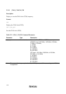
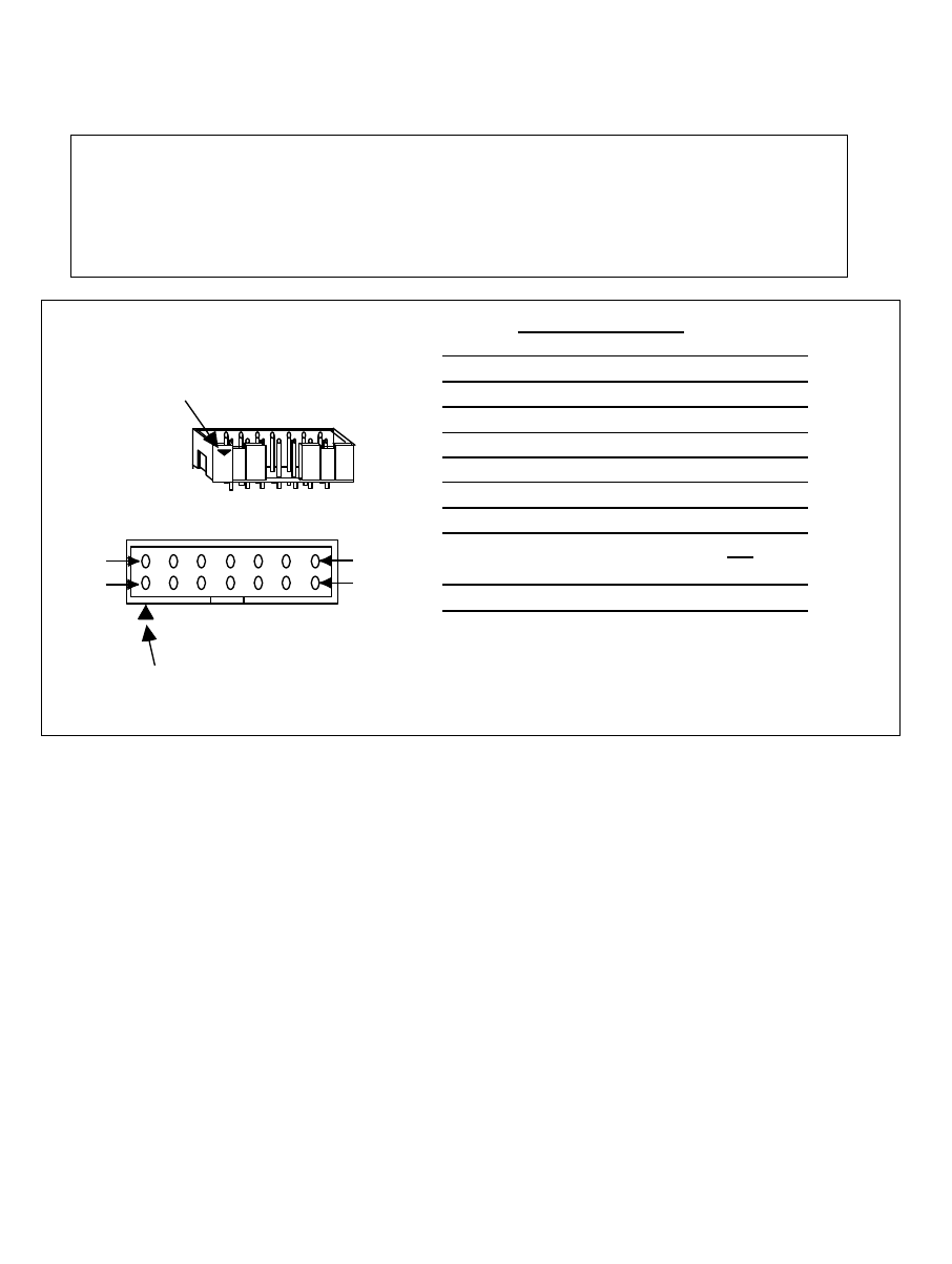
6.2 Pin Arrangement of the Hitachi-UDI Port Connector
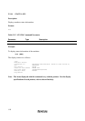
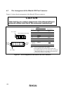
Figure 6.1 shows the pin arrangement of the Hitachi-UDI port connector.
CAUTION
Note that the pin number assignment of the Hitachi-UDI port
connector differs from that of the connector manufacturer.
Pin 1 mark
Pin 1 mark
Top view
Hitachi-UDI port connector
1 pin
8 pin
7 pin
14 pin
Pin No.
Signal
1
2
3
4
5
6
7
8 to 10
12 to 14
11
Note: 1. Input or output from the user system.
2. The symbol (#) means that the signal is active-low.
3. By detecting GND on the user system side, connection or
disconnection with the user system can be determined.
4. Connect Vcc with the Vcc of the MCU.
H8S/2377F, H8S/2367F
Input/Output *1
PG4
P53
#WDTOVF
#RES*2
PG5
PG6
#RES*2
GND*3
Vcc*4
Input
Input
Output
Input
Input
Input
Output
Input
Figure 6.1 Pin Arrangement of the Hitachi-UDI Port Connector