


121
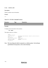
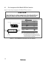
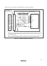
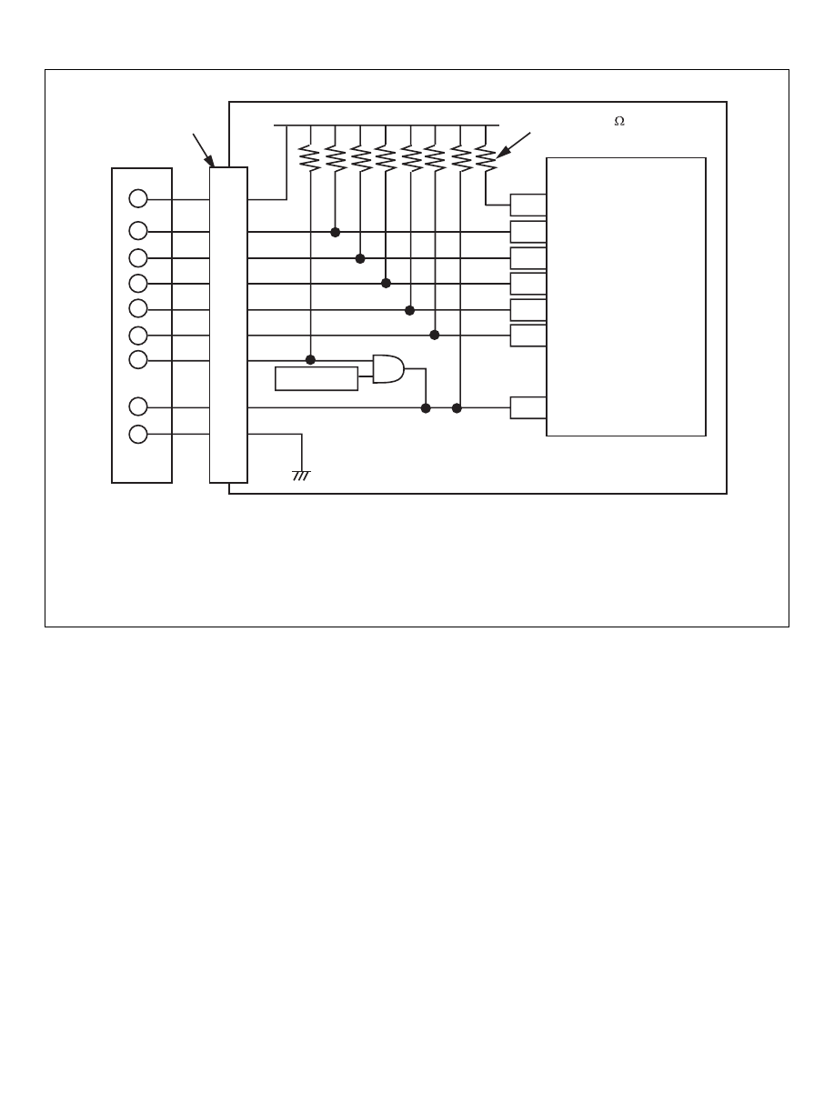
Figure 6.2 shows an example of connecting the user system to the emulator.
Pulls-up at 4.7 k
User system
User logic
Vcc
E10A pin No.
14-pin connector with
a 2.54-mm pitch
(3M Limited: 2514-6002)
· #RES of pin 4 of the Hitachi-UDI port connector is a signal line in which the emulator outputs signals to the MCU.
An AND operation must be performed between #RES (pin 4) and the user system reset circuit for the signal
line connected to the MCU.
· #RES of pin 7 of the Hitachi-UDI port connector is a signal line in which the emulator monitors the #RES signal of
the MCU. The #RES must be pulled up before it is connected to pin 7 of the Hitachi-UDI port connector.
EMLE
PG4
P53
#WDTOVF
PG5
PG6
H8S/2377F, H8S/2367F
#RES
11
1
2
3
5
6
4
7
8 to 10
12 to 14
Figure 6.2 Example of Emulator Connection