


125
6.3 Differences between the MCUs and the Emulator
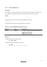
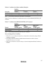
1. When the emulator system is initiated, it initializes the general registers and part of the control
registers as shown in table 6.3.
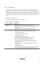
Table 6.3 Register Initial Values at Emulator Power-On
Register When Using H8S/2377F and H8S/2367F
PC Reset vector value in the vector address table
ER0 to ER6 Undefined
ER7 (SP) H'FFC000
CCR 1 for I mask, and others undefined
EXR H’07
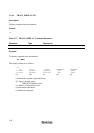
2. System Control Register
In the emulator, the internal I/O registers can be accessed from the [I/O registers] window.
However, be careful when accessing the system control register. The emulator saves the
register value of the system control register at a break and returns the value when the user
program is executed. Since this is done during a break, do not rewrite the system control
register in the [I/O Registers] window.
3. Memory Access during Emulation
If the memory contents are referenced or modified during emulation, realtime emulation
cannot be performed because the user program is temporarily halted.
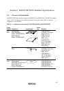
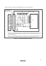
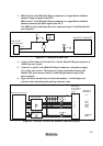
4. The emulator communicates with the MCU by using the pins shown in figure 6.1 (section 6.2).
These pins cannot be used.
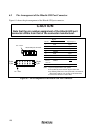
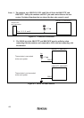
5.
The power consumed by the MCU can reach several mA. This is because the user power
supply drives one HD74LV125A to make the communication signal level match the user-
system power-supply voltage.