


M306H7T3-RPD-E User’s Manual 2. Setup
REJ10J0964-0100 Rev.1.00 August 01, 2005 Page 27 of 88
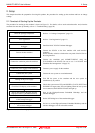
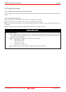
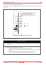
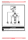
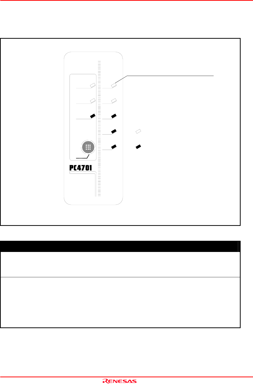
2.5.3 LED Display When the Emulator Starts Up Normally
Figure 2.5 shows front panel LED lighting status when the emulator started up properly. Check it when starting up the
emulator system.
Figure 2.5 LED display when the power turned on
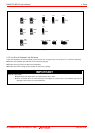
IMPORTANT
Note on the Target Status POWER LED:
If the MCU has two or more Vcc terminals, the LED does not light unless power is supplied to all the
terminals.
Note on the Target Status CLOCK LED:
If the LED is not turned on, check the following.
(1) After powering on the PC4701 (before starting up the emulator debugger):
Make sure that the oscillator circuit board is properly installed in the PC4701 and it is oscillating
normally.
(2) After the emulator debugger is started up (after the Init dialog box settings are complete):
Make sure that the oscillator selected in the Init dialog box is oscillating normally.
TARGET
STATUS OF
LED display when the emulator starts up normally
This does not light when the user
system is not connected.
: On
: Off
EMULATOR
PERFORMANCE
HIGH
HALT
STATUS OF
ERROR
POWER
SAFE
RUN
RESET
POWER
CLOCK
SYSTEM
RESET