


M306H7T3-RPD-E User’s Manual 2. Setup
REJ10J0964-0100 Rev.1.00 August 01, 2005 Page 37 of 88
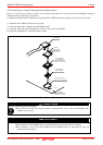
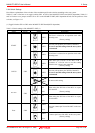
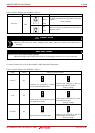
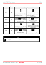
2.9.2 Each Setting
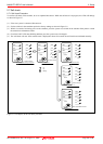
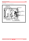
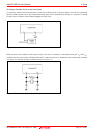
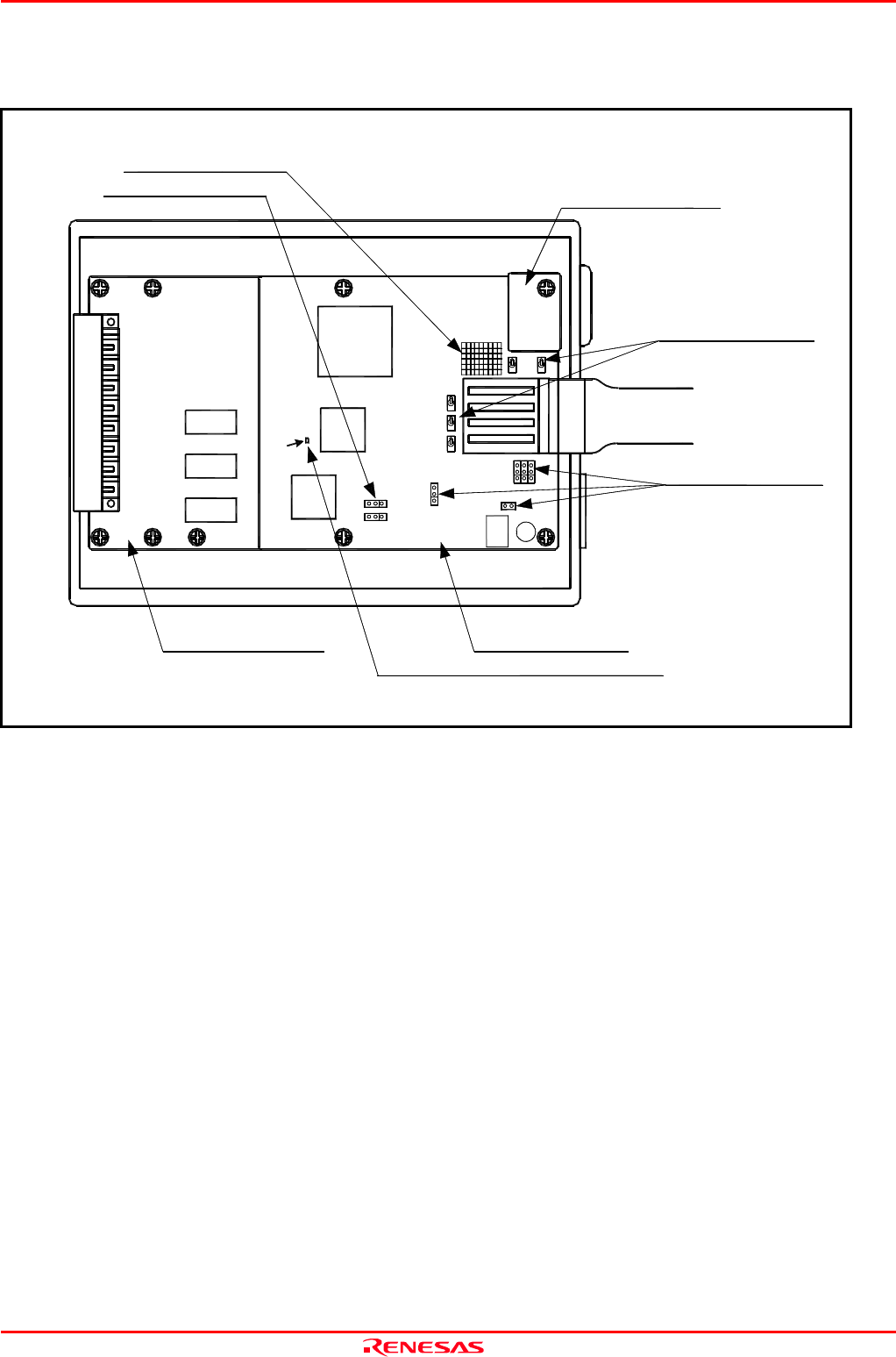
Figure 2.15 shows the positions of each part of this product.
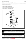
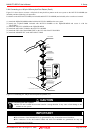
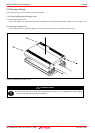
Figure 2.15 Positions of each part
MCU dependent board
Common board
(M30620T3-RPDC)
(1) Oscillator circuit board
(2) Switches
(2) Switches
(3) Socket for mounting
network resister for pullup
(4) Bypass capacitor for A/D converter
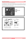
SW1
START CNVss
JP2→CVIN1
JP3→SYNCIN
JP4→SVREF
JP5→TEST3
ADDAna
V50/
TVDD
(2) Switches
JC1
P87/Xcin
Xout
P86/Xcout
VCC1
(M306H7T3-PRT)
M306H7T3-PRT REV.A
SW2
SW3
SW4
SW5
JP1JP2JP3
JC1_R
JP6
JP4
JP5
JP7
C7