


M306H7T3-RPD-E User’s Manual 2. Setup
REJ10J0964-0100 Rev.1.00 August 01, 2005 Page 42 of 88
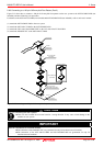
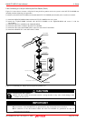
2.9.4 Switch Settings
Here follows explanations of the switches of the emulation pod. Set the switches according to the user system.
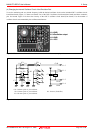
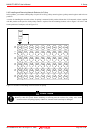
Tables 2.3 and 2.4 list how to set toggle switches SW1 to SW5 of the M306H7T3-PRT board (MCU-dependent). Tables 2.5
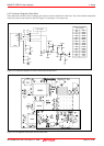
and 2.6 list how to set jumper switches JP1 to JP7 on the M306H7T3-PRT (MCU-dependent board). For the positions of the
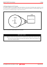
switches, see Figure 2.15.
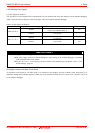
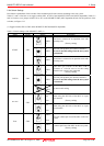
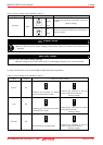
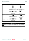
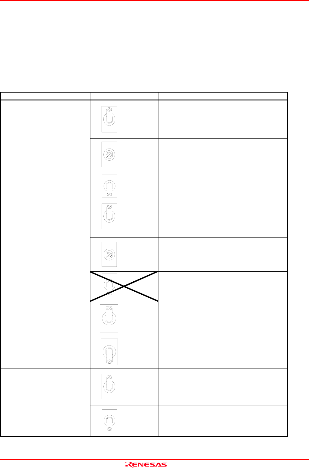
(1) Toggle Switches SW1 to SW5 on the M306H7T3-PRT Board (MCU-dependent)
Table 2.3 Switch settings of the M306H7T3- PRT (1)
Signal Switch Setting Description
L
OPEN
H
Xin-Xout is selected as an operation clock after
releasing reset.
(Factory-setting)
H
OPEN
L
Does not pull up/down pin START of the MCU.
Be sure to use this setting when the user system
is connected.
START SW1
H
OPEN
L
Xcin-Xcout is selected as an operation clock after
releasing reset.
(Factory-setting)
L
OPEN
H
Pulls down pin CNVSS of the MCU with a
resistance of 1 kΩ. Be sure to use this setting
when the user system is not connected.
(Factory-setting)
L
OPEN
H
Does not pull up/down pin CNVSS of the MCU.
Be sure to use this setting when the user system
is connected.
CNVSS SW2
L
OPEN
H
Do not use this setting.
P87
Xcin
When using the P87/Xcin of the MCU as a port
P87 function
(Factory-setting)
P87/Xcin
SW3
P87
Xcin
When using the P87/Xcin of the MCU as a port
Xcin function
OPEN
Xout
Does not connect pin Xout of the MCU to the user
system.
Xout SW4
OPEN
Xout
Connects pin Xout of the MCU to the user system.
(Factory-setting)