


M306H7T3-RPD-E User’s Manual 2. Setup
REJ10J0964-0100 Rev.1.00 August 01, 2005 Page 45 of 88
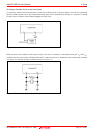
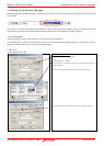
2.9.5 Installing and Removing Network Resistors for Pullup
In this product, you cannot control pullup for ports P0 to P5 by pullup control registers (pullup control register read/write are
possible).
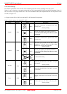
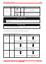
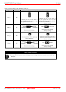
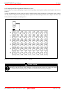
A socket for installing the network resistor for pullup is mounted in this product. Mount the 51 kΩ network resistor supplied
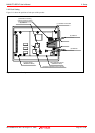
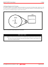
with this product to the port for which pullup control is required. For the mounting location, refer to Figure 2.21 below. And
for the positions of each part, refer to Figure 2.15.
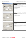
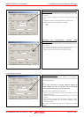
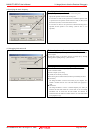
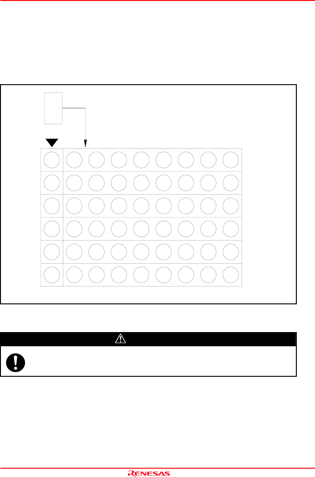
Figure 2.21 Position for mounting network resistors for pullup
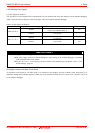
CAUTION
Note on Installing and Removing Network Resistors for Pullup:
Always shut OFF power before installing or removing network resistors for pullup. Also install
network resistors for pullup properly. Otherwise, internal circuit board may be damaged.
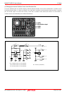
VCC
P5 P4 P3 P2 P1 P0
RM1
--
RM6
VCC
VCC
VCC
VCC
VCC
VCC
P07 P06 P05 P04 P03 P02 P01 P00
P17 P15P16 P14 P10P13 P12 P11
P37
P27
P35P36 P34
P25P26 P24
P30
P20
P33 P32 P31
P23 P22 P21
P57 P55P56 P54
P47 P45P46 P44
P50P53 P52 P51
P40P43 P42 P41