


M306H7T3-RPD-E User’s Manual 2. Setup
REJ10J0964-0100 Rev.1.00 August 01, 2005 Page 44 of 88
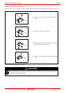
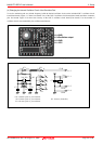
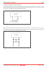
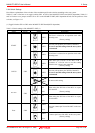
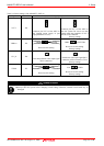
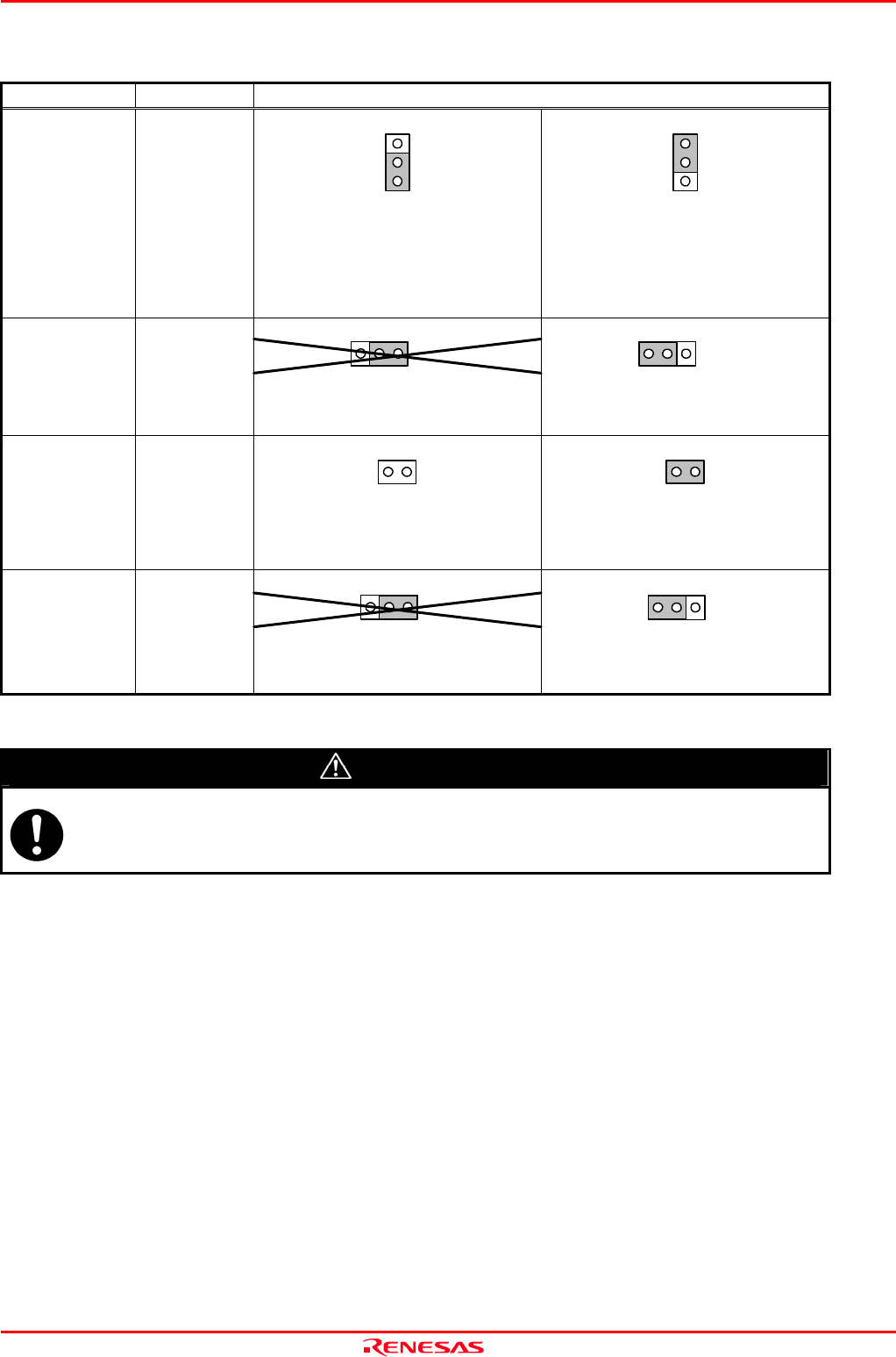
Table 2.6 Switch settings of the M306H7T3- PRT (4)
Signal Switch Setting of jumper switches
FLX FLX
INT INT
VCC1 JP4
Connects pin VCC1 of the MCU to
the internal power supply of pod
(equipotential of VCC2).
Connects pin VCC1 of the MCU to
the user system. Be sure to use this
setting when the potentials of VCC1
and VCC2 are different.
(Factory-setting)
VDD2 V50/TVDD
VDD2
V50/TVDD
VDDAna JP5
Do not use this setting.
Be sure to use this setting.
(Factory-setting)
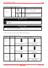
JC1_R JC1_R
JC1_R JP6
Does not pull down video input signal
(RCA connector).
Pulls down video input signal (RCA
connector) with a resistance of 75 Ω
(Factory-setting)
V50 TVDD
V50
TVDD
TVDD JP7
Do not use this setting.
Be sure to use this setting.
(Factory-setting)
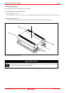
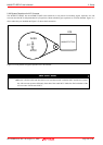
CAUTION
Note on Switch Settings:
Always shut OFF power before changing switch setting. Otherwise, internal circuit board may be
damaged.