


M306H7T3-RPD-E User’s Manual 2. Setup
REJ10J0964-0100 Rev.1.00 August 01, 2005 Page 35 of 88
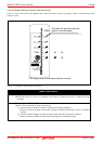
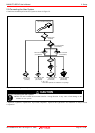
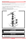
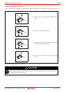
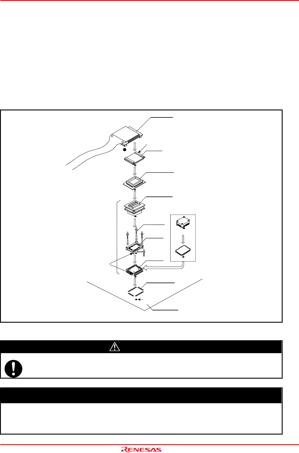
2.8.4 Connecting to a 100-pin 0.65-mm-pitch Foot Pattern (Part 3)
Figure 2.13 shows how to connect a 100-pin 0.65-mm-pitch foot pattern on the user system to the M3T-FLX-100NRB (not
included), and here following is its procedure.
For details on the M3T-100LCC-DMS (not included) and M3T-FLX-100NRB (not included), refer to each user's manual.
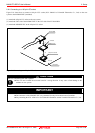
(1) Attach the NQPACK100RB included with the M3T-FLX-100NRB to the user system.
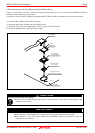
(2) Attach the YQPACK100RB included with M3T-FLX-100NRB to the NQPACK100RB and secure it with the
YQ-GUIDE's.
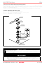
(3) Attach the M3T-FLX-100NRB to the YQPACK100RB.
(4) Attach the M3T-100LCC-DMS to the M3T-FLX-100NRB
(5) Attach the CN2 side of the M30800T-PTC to the CN2 side of the FLX160-PRB.
(6) Attach the M30800T-PTC to the M3T-100LCC-DMS.
Figure 2.13 Connecting to a 100-pin 0.65-mm-pitch foot pattern (3/3)
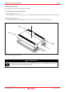
CAUTION
Note on Connecting the User System:
Take care not to attach the converter board in a wrong direction. It may cause a fatal damage to the
emulator or user system.
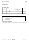
IMPORTANT
Notes on Connectors of Converter Boards:
The connectors of the M30800T-PTC are guaranteed for only 50 insertion/removal iterations.
The connectors of the M3T-100LCC-DMS and M3T-FLX-100NRB are guaranteed for only 20
insertion/removal iterations.
M3T-100LCC-DMS
(not included)
CN2 side
(5)
M30800T-PTC
(1)
100-pin 0.65-mm-pitch
(PRQP0100JB-A) foot pattern
No.1 pin
M3T-FLX-100NRB
(not included)
FLASH MCU etc
On-board evaluation
* : These four products are available in one package.
YQPACK100RB
NQPACK100RB
HQPACK100RB168
(not included)
These corners are not round.
(2)
(3)
(6)
(4)
YQ-GUIDE(x4)
*
FLX160-PRB
User system