


M306H7T3-RPD-E User’s Manual 2. Setup
REJ10J0964-0100 Rev.1.00 August 01, 2005 Page 38 of 88
2.9.3 Selecting Clock Supply
(1) Clock Supply to the MCU
You can choose a clock supplied to the evaluation MCU by the Emulator tab in the Init dialog box of the emulator debugger.
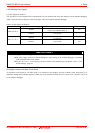
Table 2.2 lists the factory-settings of each clock supply when you install the emulator debugger.
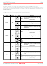
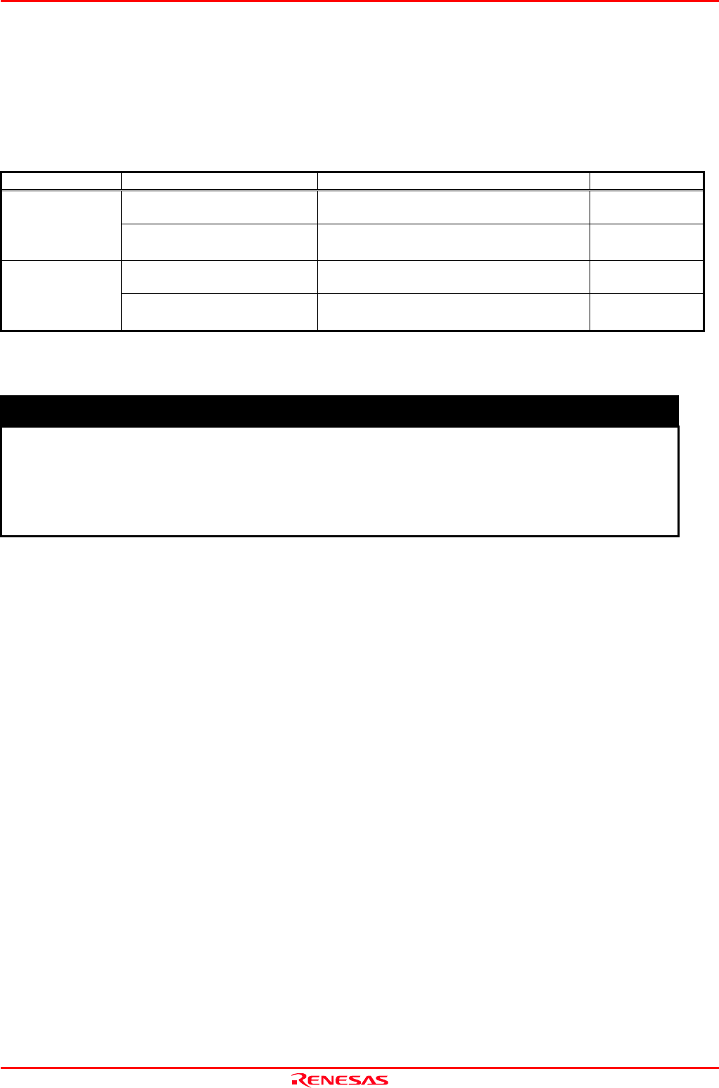
Table 2.2 Clock Supply to the MCU
Clock Display of emulator debugger Description Default setting
Internal
Internal oscillator circuit of emulation pod
(OSC-3: 16.0 MHz or OSC-2)
Yes
Main (XIN-XOUT)
External User system -
Internal
Internal oscillator circuit of emulation pod
(32.768 kHz)
-
Sub (XCIN-XCOUT)
External User system Yes
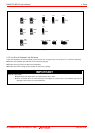
IMPORTANT
Note on Changing the Clock Supply:
The clock supply can be set in the Init dialog box when starting up the emulator debugger or inputting
CLK command on the script window.
For pins X
CIN
-X
COUT
, it is necessary to set the switches in the emulation pod. For details, refer to "2.9.4
Switch Settings" (page 42)
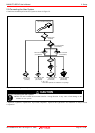
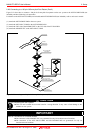
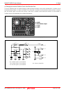
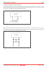
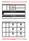
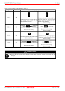
(2) Using the Internal Oscillator Circuit Board
An oscillator circuit board for 16.0 MHz (OSC-3) is mounted on this product. Also the oscillator circuit board (OSC-2) is
attached to change the oscillation frequency. When you use an internal oscillator circuit as a main clock, “Internal” can be set
by the emulator debugger.