


M306H7T3-RPD-E User’s Manual 2. Setup
REJ10J0964-0100 Rev.1.00 August 01, 2005 Page 47 of 88
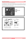
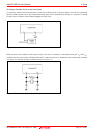
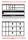
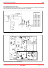
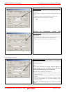
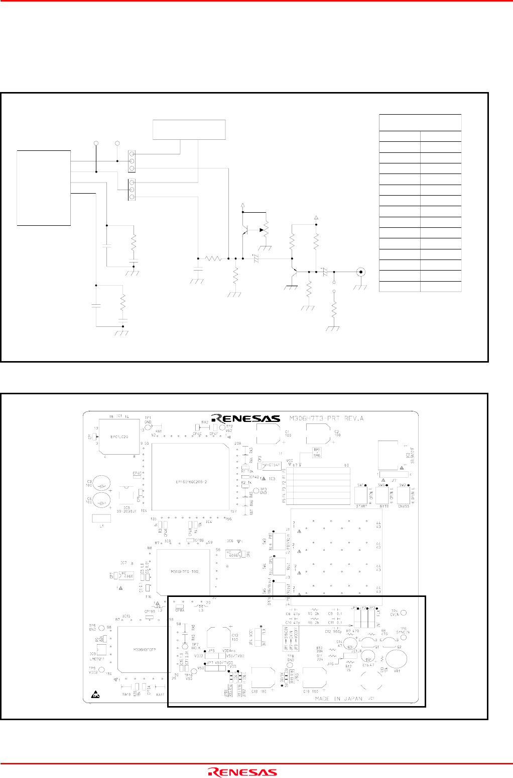
2.9.7 Connection Diagram of Data Slicer
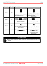
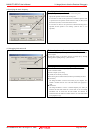
This product has on-board sockets to change parts used for circuits connected to a data slicer. The circuit and the arrangement
of the parts used for each circuit are shown in Figure 2.23 and Figure 2.24, respectively.
Figure 2.23 Connection diagram of circuits connected to the data slicer
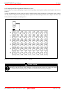
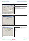
Figure 2.24 Arrangement of the parts used for each circuit
C15
C8
R5
C9
C10
C11
R6
SYNCIN
CVIN
LP3
LP4
PER-E
109
108
112
103
JP1
JP2
C14
C12
R13
R7
Q1
R11
R8
VR1
R10
VDDAna
VDDAna
R12
JC1
JP6
C12
C15
C14
560pF
47μF
47μF
470Ω
R7
75Ω
R12
C10
C11
C9
C8
47pF
0.1μF
0.1μF
47pF
R13
R11
R8
R10
10kΩ
22kΩ
39kΩ
470Ω
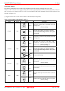
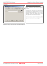
Resistance and capacity
Factory-settings
R5
R6
2kΩ
2kΩ
Q2
TP4TP6
User system