


M306H7T3-RPD-E User’s Manual Contents
REJ10J0964-0100 Rev.1.00 August 01, 2005 Page 9 of 88
Contents
Page
Preface......................................................................................................................................................................... 3
Related manuals.......................................................................................................................................................... 3
Important...................................................................................................................................................................... 4
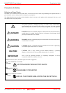
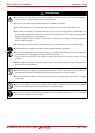
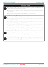
Precautions for Safety .................................................................................................................................................6
Contents....................................................................................................................................................................... 9
User Registration ....................................................................................................................................................... 11
Terminology................................................................................................................................................................12
1. Outline.................................................................................................................................................................... 13
1.1 Package Components .................................................................................................................................. 13
1.2 Other Tool Products Required for Development........................................................................................... 14
1.3 System Configuration ................................................................................................................................... 15
1.3.1 System Configuration........................................................................................................................... 15
1.3.2 Names and Functions of the PC4701 Front Panel LEDs .................................................................... 16
1.4 Specifications................................................................................................................................................ 18
1.5 Operating Environment.................................................................................................................................19
2. Setup......................................................................................................................................................................20
2.1 Flowchart of Starting Up the Emulator..........................................................................................................20
2.2 Installing the Emulator Debugger (M16C PC4701 Emulator Debugger)...................................................... 21
2.2.1 Installing the Emulator Debugger ........................................................................................................ 21
2.3 Connecting the Host Machine ......................................................................................................................22
2.4 Connecting the PC4701 ............................................................................................................................... 23
2.4.1 Connecting the Cable to the PC4701 ..................................................................................................23
2.4.2 Connecting the FLX120-RPD to the Emulation Pod............................................................................ 24
2.4.3 PC4701 and Emulation Pod Arrangement...........................................................................................25
2.5 Turning ON the Power..................................................................................................................................26
2.5.1 Checking the Connections of the Emulator System ............................................................................ 26
2.5.2 Turning ON/OFF the Power .................................................................................................................26
2.5.3 LED Display When the Emulator Starts Up Normally..........................................................................27
2.6 Downloading Firmware................................................................................................................................. 28
2.6.1 When It is Necessary to Download Firmware...................................................................................... 28
2.6.2 Downloading Firmware in Maintenance Mode.................................................................................
.... 28
2.7 Self-check..................................................................................................................................................... 29
2.7.1 Self-check Procedure........................................................................................................................... 29
2.7.2 If an Error is Detected in the Self-check .............................................................................................. 30
2.8 Connecting the User System........................................................................................................................31
2.8.1 Connecting to a 100-pin LCC socket................................................................................................... 32
2.8.2 Connecting to a 100-pin 0.65-mm-pitch Foot Pattern (Part 1)............................................................. 33
2.8.3 Connecting to a 100-pin 0.65-mm-pitch Foot Pattern (Part 2)............................................................. 34
2.8.4 Connecting to a 100-pin 0.65-mm-pitch Foot Pattern (Part 3)............................................................. 35
2.9 Changing Settings ........................................................................................................................................ 36
2.9.1 Removing/Attaching the Upper Cover .................................................................................................36
2.9.2 Each Setting......................................................................................................................................... 37
2.9.3 Selecting Clock Supply ........................................................................................................................38
2.9.4 Switch Settings .................................................................................................................................... 42
2.9.5 Installing and Removing Network Resistors for Pullup........................................................................ 45
2.9.6 Bypass Capacitors for A/D Converter .................................................................................................. 46
2.9.7 Connection Diagram of Data Slicer ..................................................................................................... 47