


ULTRAMATRIX “UMX” SERIES INSTALLATION AND OPERATIONS MANUAL
6
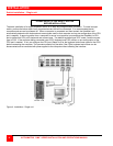
To expand the UltraMatrix switch in an expanded configuration, an expansion card must be installed in each
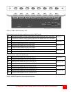
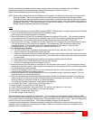
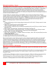
UltraMatrix switch. Figure 2 shows the expansion card used for the “4X” model, Figure 3 shows the expansion card
used for the 8X and 16X models. The 16X model has an upper and lower expansion card installed.
Out 1 and In 1 connectors on the expansion card transmit and receive all keyboard, mouse and system signals and
the video signals for KVM 1 and KVM 2. In an expanded system, expansion cables must be connected from the
Out 1 connector on one unit to the In 1 connector on another unit for the expanded system to work because all
system control information is transmitted and received from these ports.
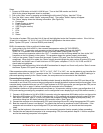
Jumper JP3 or JP15 must be removed from the expansion cards on two Units in the RING topology to properly
maintain cable termination. To identify which Units must have jumper JP3 or JP15 removed, calculate the total cable
length around the “RING”. This is from Unit #1’s “IN” connector, around the “RING” and back to Unit #1’s “OUT”
connector.
Jumper JP15 (UM4 model) or JP3 (UM8 model and UM16 model-lower card) should be removed on Unit #1 and
another switch in the system that will divide the “RING” into approximately equal cable length distances.
To remove an expansion card and install/remove any jumpers, perform the following:
1. Remove power from the UltraMatrix switch.
2. Remove any expansion cables. (Note the connectors they are attached to)
3. Unscrew the two screws securing the expansion card to the chassis.
4. Carefully pull the expansion card straight back until it unseats from the backplane connector.
5. Remove/install the needed jumpers (JP15 on the 4X model / JP1, JP2 or JP3 on the 8X/16X models)
6. Re-install the expansion card. Make sure it seats properly in the backplane connector.
7. Secure the expansion card with the two screws.
8. Replace the expansion cables to the correct connectors.
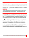
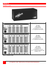
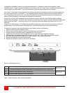
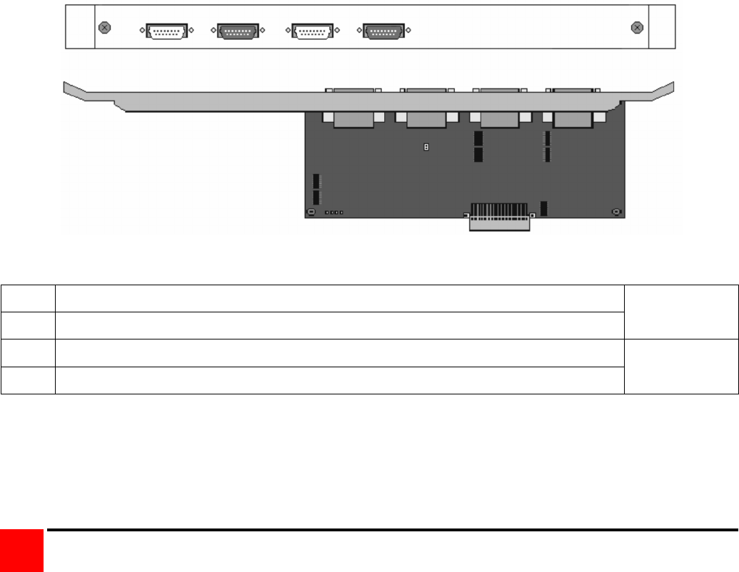
Figure 2. UM4 Expansion card
IN1 Receives all keyboard, mouse, system data and video signals for KVM 1 and KVM2
OUT1 Transmits all keyboard, mouse, system data and video signals for KVM 1 and KVM2
BUS 1 & 2
IN2 Receives video signals for KVM 3 and KVM 4
OUT2 Transmits video signals for KVM 3 and KVM 4
BUS 3 & 4
Table 1. UM4 Expansion card connector description
OUT2 IN2 OUT1 IN1
IN1 OUT1 IN2 OUT2
JP15
JUMPER OFF-RING
JUMPER ON-BUS