


ULTRAMATRIX “UMX” SERIES INSTALLATION AND OPERATIONS MANUAL
37
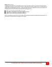
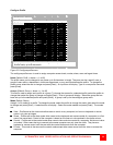
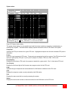
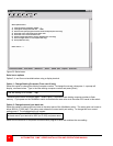
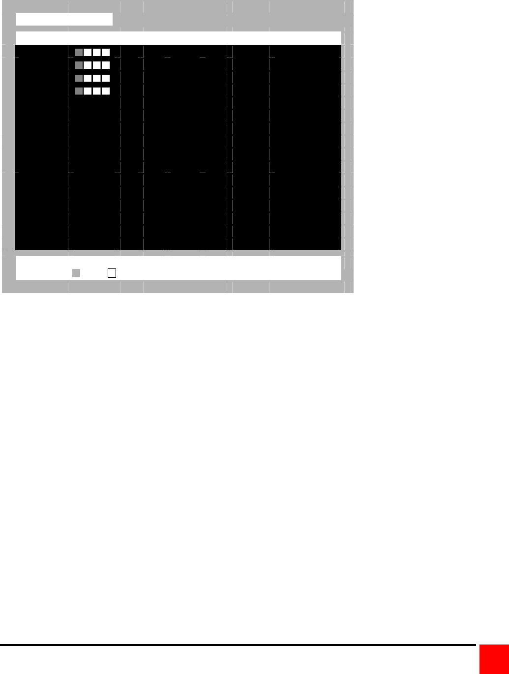
System status
System status
Computers
Power Pos Ver KVM CPU User Status
1-4
1
22 PC 1
User 1 View mode
5-8
2
22 PC 2
User 2 Share mode
9-12
3
22 PC 3
User 3 Share mode
13-16
4
22 Sun 4
User 4 Share mode
17-20 No response
21-24 No response
25-28 No response
29-32 No response
33-36 No response
37-40 No response
41-44 No response
15-48 No response
19-52 No response
53-56 No response
57-60 No response
61-64 No response
Pos = Card position | Ver = Program version | KVM = PC/Sun/None
CPU power = on = off | Line color
Good Disconnected Error
Figure 25. System status display
The system status display is a very powerful and useful tool when monitoring, expanding, troubleshooting, or
reconfiguring a system. The status screen displays reported information from all CPU cards in the system.
Computers
Indicates the CPU port numbers for a given CPU card. Highlighted computers are the total connected CPU ports in
the system.
Power
Each CPU card represents 4 CPU ports. These ports are represented by the four squares. The CPU ports are (Left
square to right square), CPU port 1, port 2, port 3, and port 4. (Green = CPU is on, Red = CPU is off)
Pos (Position)
Displays the slot where a CPU card in the system is installed for a given switch. Slot 1 is the bottom CPU card.
Ver (Version)
Displays the last three digits of the firmware main program version for the CPU card.
KVM
Indicates the type of keyboard and mouse detected if a KVM station is attached to this CPU card.
CPU
Displays the computer number currently selected by the KVM station.
User
Displays the users name that is currently accessing the system.
Status
Displays the most recent connect or disconnect status for the KVM station on this CPU card.