


ULTRAMATRIX “UMX” SERIES INSTALLATION AND OPERATIONS MANUAL
18
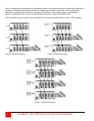
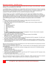
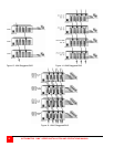
Multi-switch installation – Split BUS topology
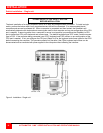
Refer to Figure 11 for a typical split BUS topology for the UM4 model, and Figure 12 for the UM8 model. A split BUS
topology is not recommended for the UM16 model.
In a split BUS topology, the KVM stations are usually located on the first unit and the last unit. In Figure 11, the video
path for KVMs 1 and 2 is routed from the last unit (OUT 1) to the first unit (IN 1). The reverse is done for KVMs 3 and
4, the video path is routed from the first unit (OUT 2) to the last unit (IN 2). KVMs 1 and 2 can connect to all
computers in the system, and KVMs 3 and 4 can connect to all computers in the system.
To begin setting up your system in a “Split BUS” topology, first pre-configure each UltraMatrix with its “Starting
computer” number (See page 11). When the “Starting computer” number has been entered for each Unit, determine
the KVM assignment jumper settings (JP1 and JP2) for the UM8 models and set them accordingly. The UM4 model’s
KVM assignment is fixed and not user selectable. (See Figure 3 and Table 2) When the “Starting computer number
and the KVM assignment jumpers, JP1 and JP2 have been set, the expansion cables can be connected.
Steps:
1. Connect a KVM station to Unit #1’s KVM #1 connector and apply power to the monitor and Unit #1.
2. Call up the “main menu (left [Ctrl] key, then the F12 key).
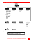
3. Select “Status” from the main menu and press [Enter]. The system status screen will display showing the
following; (Figure 25)
1. Computers
2. Power (Power on status)
3. POS (Card position)
4. VER (Program version)
5. KVM
6. CPU
7. User
8. Status
The number of system CPU ports that Unit #1 has will be highlighted. If the unit is a 8-port switch, computers
1-4, and 5-8 will be highlighted on the status screen.
(NOTE: System CPU ports = total RS/232 ports times 4)
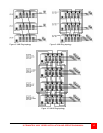
4. Apply power to the next unit to bus in, then connect an expansion cable (IN THIS ORDER);
From: Unit #2’s “OUT 1” expansion card connector,
To: Unit #1’s “IN 1” expansion card connector.
5. Verify on the status screen that the next block of system CPU ports from Unit #2 is recognized. If Unit #2 is an 8-
port switch, computers 17-20 and 21-24 will be highlighted.
6. Sequentially apply power then connect the expansion cables to the remaining switches as explained in steps 4.
Always with power on the unit and from the “OUT” connector of the Unit being added to the “IN” connector of the
previously installed Unit.
Steps 4-6 route the video from all units to the KVM ports on Unit #1. Now the reverse must be performed to route the
video from all units to KVM ports on the last unit.
For the steps below, the example in Figure 11 is used. Unit #3 is the last unit in the configuration, Unit #2, the next to
last unit and so on.
7. Connect a KVM station to Unit #3’s KVM 4 connector and apply power to the monitor. (All UltraMatrix switches
power should be ON)
8. Connect an expansion cable
From: Unit #2’s “OUT 2” expansion card connector,
To: Unit #3’s “IN 2” expansion card connector.
9. Cable in the remaining switches as explained in step 9 from the “OUT 2” connector to the “IN 2” connector. Verify
that the status screen report correctly.
10. Connect the expansion cables for the other IN/OUT ports.
Steps 7-10 complete the expansion cabling for a “Split Bus” configuration. KVMs connected to Unit #1 can access all
computers in the system. KVMs connected to the last unit’s can access all computers in the system.