


ULTRAMATRIX “UMX” SERIES INSTALLATION AND OPERATIONS MANUAL
12
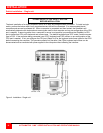
Multi-switch installation – General
The UltraMatrix switch can be installed in a variety of expanded topologies. The BUS, RING, Split BUS, and
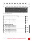
Staggered BUS are the most common configurations. In any expanded system, each expansion port pair (Out1/ IN1)
on an expansion card carry the video information for two KVM stations (See Table 1 and Table 2). A KVM station
can connect to any computer, provided that KVM station’s video path has been routed to the corresponding
expansion port on the switch that the computer is connected to. When the expansion cable path terminates, the
video path for that KVM pair stops. Examples of the cabling and configuration of these four topologies are explained
for each of the three UltraMatrix models.
To begin installing any expanded topology, each UltraMatrix switch must be pre-configured with its “Starting
computer” number. In the following examples, the “Starting computer” number for Unit #1 is always 1 (default value).
Unit #2’s starting computer number is the total number of RS232 ports on Unit #1 times 4 plus 1. Using all 16 CPU
port models, the number for the second unit would be 17. (4-RS232 ports times 4 plus 1). Unit #3’s “Starting
computer” number would be 33. (Number of RS232 ports on Unit #1 plus those on Unit #2 times 4 plus 1.)
Configure the “Starting computer” number for each switch as follows:
Steps:
1. Connect a KVM station to the Unit being configured (starting with Unit #2, Unit #1’s “Starting computer” number
is, by default, 1)
2. Apply power to the KVM monitor and the UltraMatrix switch
(Wait for the internal diagnostic check to complete)
3. Call-up the “Main” configuration menu by pressing and releasing the left control [Ctrl] key, and within 2 seconds,
press the F12 key.
4. Select “System” and press [Enter]. The system menu will display. (See Figure 18)
5. Select “Starting computer” number and press [Enter]. An input box will display for a new “Starting computer”
number. Type in the correct “Starting computer” number for this Unit and press [Enter].
6. Press the “Esc” key to return to the “Main” menu.
7. Select “Save” and press [Enter]. A “YES/NO” choice box will display. Select “YES” and press [Enter] to save the
changes. (See Figure 26)
8. Turn the power off on the UltraMatrix.
9. Connect the KVM station to the next unit to configure.
10. Perform steps 2-9 for this Unit and for all Units in the system.
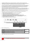
When all Units have their correct “Starting computer” number assigned, the expansion cables can be connected.
The expansion cables carry the system and video signals from one Unit’s OUT connector to another Unit’s IN
connector. When the “Starting computer” number has been entered for each Unit, determine the KVM assignment
jumper settings (JP1 and JP2 for the UM8 and Um16 models) and set them accordingly. The UM4 model’s KVM
assignment is fixed and not user selectable. (See Figure 3, Table 2, and KVM assignment information on page 6)
When the “Starting computer number and the KVM assignment jumpers, JP1 and JP2 have been set, the expansion
cables can be connected.
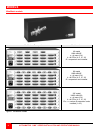
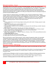
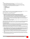
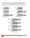
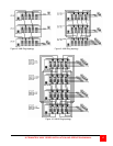
Multi-switch installation – BUS topology
Refer to Figure 5 for a typical BUS installation for the UM4 model, Figure 6 for the UM8 model, and Figure 7 for the
UM16 model.
The BUS installation is very similar to the single unit installation with the addition of connecting the expansion cables
and changing two configuration parameters, the “Starting computer” number for each unit and the “Maximum
computers” number.
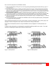
In a BUS topology, KVM stations on Unit #1 can access all computers. KVMs on Unit #2 can access all computers
except those on Unit #1. KVMs on Unit #3 can access all computers except those on Unit #2 and Unit #1.
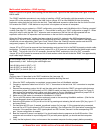
The recommended way to connect the expansion cables is to use the system “Status” display to verify the
connections. Following explains how to use the “Status” display and what to verify.