


ULTRAMATRIX “UMX” SERIES INSTALLATION AND OPERATIONS MANUAL
13
Steps:
1. Connect a KVM station to Unit #1’s KVM #1 port. Turn on the KVM monitor and Unit #1.
(Wait for the internal diagnostic check is complete)
2. Call-up the “Main” menu by pressing and releasing the left control [Ctrl] key, then the F12 key.
3. From the “Main” menu, select “Status” and press [Enter]. The system “Status” display will appear.
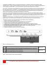
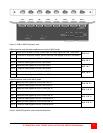
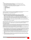
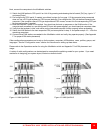
The “Status” display shows the following information. (See Figure 25)
a. Computers
b. Power (Power on status)
c. POS (Card position)
d. VER (Program version)
e. KVM
f. CPU
g. User
h. Status
The number of system CPU ports that Unit #1 has will be highlighted under the Computers column. If the Unit is a
16-port Unit, computers 1-4, 5-8, 9-12, and 13-16 will be highlighted on the status screen.
(Note: “System CPU ports” = the total RS232 ports times 4)
BUS in the expansion Units as outlined in below steps:
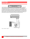
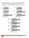
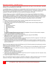
4. Apply power to the Unit to BUS in, then connect the expansion cables (IN THIS ORDER):
From the “OUT 1” expansion card connector on the Unit being added (Starting with Unit #2);
To the “IN 1” expansion card connector on the Unit already added (Starting with Unit #1).
(Always connect an expansion cable to the “OUT 1” connector on the Unit being added first, then to the “IN 1”
connector on the Unit already in the system. This procedure keeps the system properly terminated).
5. Verify on the system “Status” screen that the correct “System CPU ports” from the Unit being added is
recognized. When Unit #2 is added, the “Status” display should highlight the total number of system CPU ports
that Unit #1 and Unit #2 have. If both Units have 16 CPU ports, computers 17-20, 21-24, 25-28, and 29-32
should also be highlighted.
6. Sequentially add the remaining Units to the BUS as described in steps 4 and 5 and verify on the “Status” screen
that these “System CPU ports” are recognized.
Other expansion cables connected from “OUT 2” to “IN 2”, “OUT 3” to “IN 3”, etc. can be added at any time after the
expansion cables from the “OUT 1” connector to the “IN 1” connector have been added. When all BUS cabling is in
place and reporting correctly to the “Status” screen, the computers can be connected to the UltraMatrix.
Connecting the computers
The computers that will be connected the UltraMatrix should already be identified as to what CPU port they will be
connected to and if that CPU port must be pre-configured to change the default keyboard and/or mouse types. If the
computer being connected does not use a PC2 type keyboard or a PS/2 type mouse, pre-configure that CPU port as
described in step 5 a-f on page 11 before connecting the computer to the UltraMatrix.
(All UltraMatrix switches in the system should have power on, all expansion cabling in place, pre-configuration of all
CPU ports needing pre-configuring completed, and no configuration menu displaying on any KVM stations monitor.)
7. Connect a KVM station to Unit #1’s KVM #1 connector using the appropriate KVM cable and turn on the monitor.
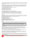
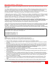
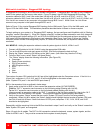
8. Switch the KVM station to CPU port # “x” (starting with x=1) by pressing and releasing the left control [Ctrl] key,
then within 2 seconds, type in 1 (or the CPU port # the computer is being connected to) and press [Enter]. A
connection dialog box will display showing the connection status. (See Figure 29)
9. Connect the computer to its corresponding CPU port # (starting with port #1) using the appropriate CPU cable.
10. Boot the computer if power is not applied. You should see the boot-up sequence on the KVM monitor. If the
computer was connected to a pre-configured CPU port with power applied, you should see that computers
video.
11. Verify that the keyboard, video and mouse on the connected computer function properly before proceeding.
12. Connect the next sequential computer to its corresponding CPU port and perform steps 8-11 for this computer
and for the remaining computers in the system.