


ULTRAMATRIX “UMX” SERIES INSTALLATION AND OPERATIONS MANUAL
21
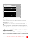
Following explains the additional expansion cabling needed for each model in a Staggered BUS topology.
Steps 1-6 route the signals from all UltraMatrix switches to Unit #1, KVMs 1 and 2. The next step is to properly route
all signals to the other KVM stations. Make sure all UltraMatrix switches have power on.
Connecting the remaining cables for all models depends on the KVM placement.
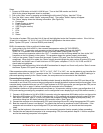
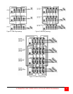
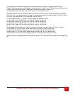
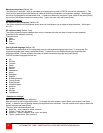
On the UM4 model, route the expansion cables from all Units to the Unit KVM 3 and 4 are going to be connected
(OUT 2 to IN 2). In the example shown in Figure 13, the expansion cables are connected from Unit #3 to #2, #2 to
#1, and #1 to #4 where KVMs 3 & 4 are located. (Refer to Table 1)
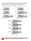
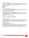
The UM8 model shown in Figure 14, routes all signals to: (Refer to Table 2)
Unit #1, KVMs 1 and 2 (OUT1 to IN1): Unit #4 to #3, #3 to #2, and #2 to #1.
Unit #2, KVMs 3 and 4 (OUT2 to IN2): Unit #1 to #4, #4 to #3, and #3 to #2.
Unit #3, KVMs 5 and 6 (OUT3 to IN3): Unit #2 to #1, #1 to #4, and #4 to #3.
Unit #4, KVMs 7 and 9 (OUT4 to IN4): Unit #3 to #2, #2 to #1, and #1 to #4.
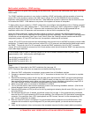
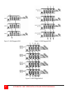
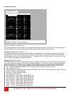
The Staggered BUS topology for the UM16 model shown in Figure 15 routes all signals to: (Refer to Table 2)
Unit #1, KVMs 1-4 (OUT1/2 to IN1/2 Lower card from Unit #4 to #3, #3 to #2, and #2 to #1)
Unit #2, KVMs 5-8 (OUT3/4 to IN3/4 Lower card from Unit #1 to #4, #4 to #3, and #3 to #2)
Unit #3, KVMs 9-12 (OUT5/6 to IN5/6 Upper card from Unit #2 to #1, #1 to #4, and #4 to #3)
Unit #4, KVMs 13-16 (OUT7/8 to IN7/8 Upper card from Unit #3 to #2, #2 to #1, and #1 to #4)
These examples of a Staggered BUS are provided as a guide to show how flexible and versatile this topology can
be.