


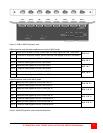

ULTRAMATRIX “UMX” SERIES INSTALLATION AND OPERATIONS MANUAL
15
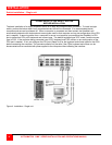
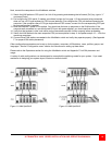
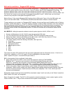
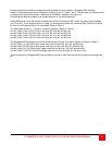
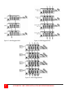
Multi-switch installation – RING topology
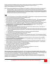
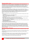
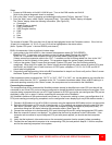
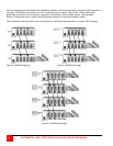
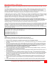
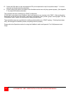
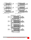
Refer to Figure 8 for a typical RING topology for the UM4 model, Figure 9 for the UM8 model, and Figure 10 for the
UM16 model.
The “RING” installation procedure is very similar to installing a “BUS” configuration with the exception of removing
jumper JP3 on the expansion cards on two UM4 Units or jumper JP15 on two UM8/UM16 Units and adding
expansion cables from the first Unit to the last Unit. These additional expansion cables from the first Unit to the last
Unit creates the “RING”. KVM stations on any switch in the system can access all computers.
To begin setting up your system in a “RING” configuration, pre-configure each UltraMatrix with its “Starting computer”
number (See page 12). Next, perform steps 1 – 6 as outlined in setting up a “BUS” configuration on page 12. When
doing this, keep in mind that the “OUT” expansion card connectors on the first Unit will be connected with an
expansion cable to the “IN” expansion card connectors on the last Unit to complete the “Ring”.
When the “Starting computer” number has been entered for each Unit, determine the KVM assignment jumper
settings (JP1 and JP2) for the UM8 and Um16 models and set them accordingly. The UM4 model’s KVM assignment
is fixed and not user selectable. (See Figure 3 and Table 2) When the “Starting computer number and the KVM
assignment jumpers, JP1 and JP2 have been set, the expansion cables can be connected.
Jumper JP3 or JP15 must be removed from the expansion cards on two Units in the RING to properly maintain cable
termination. To identify which Units must have jumper JP3 or JP15 removed, calculate the total cable length around
the “RING”. This is from Unit #1’s “IN” connector, around the “RING” and back to Unit #1’s “OUT” connector.
Jumper JP3 or JP15 should be removed on Unit #1 and another switch that will divide the “RING” into approximately
equal cable length distances.
Steps:
(Perform steps 1-6 described in the “BUS” installation first (see page 12).
NOTE: Disconnect the cables from an expansion card before removing the card
1. When the “BUS” configuration is completed, remove power from all UltraMatrix switches.
2. Connect an expansion cable from Unit #1’s “OUT 1” connectors to the last Units “IN1” connectors to complete
the “Ring”.
3. Remove the expansion card on Unit #1 and the other switch that divide the “RING” into equal cable distances
and remove jumper JP3 (UM4 model) or JP15 (UM8/16 model) on these two units (See Figure 2 or Figure 3),
then replace the expansion cards, cables, and apply power to the two UltraMatrix switches that jumper JP3 or
JP15 was removed. All other UltraMatrix switches should have power off at this time.
4. Make sure a KVM station is connected to UltraMatrix #1, KVM #1.
5. Turn on all KVM stations video monitors and apply power to the remaining UltraMatrix switches. (Wait for the
internal diagnostic check to complete and fade out).
6. Switch the KVM station to CPU port #1 on Unit #1 by pressing and releasing the left control [Ctrl] key, type in “1”
and press [Enter].
7. Pre-configure the CPU port, if needed, as outlined in steps 5a-f on page 11 if the computer being connected
does not use a PC2 type keyboard or PS/2 mouse (defaults). Pre-configure the CPU port before connecting the
computer. If the computer uses a PC2 type keyboard and PS/2 mouse, connect it to the corresponding CPU
port. No pre-configuration is needed.
8. Boot the computer if power is not applied. You should see the boot up sequence on the KVM monitor. If the
computer was connected to a pre-configured CPU port with power applied, you should see that computers
video.
9. Verify that the keyboard, video, and mouse on the connected computer function properly before proceeding.
In the example used in Figure 8, removing jumper JP3 on Unit #1 and #3 divides the total ring cable length
approximately in half. Assuming the cable lengths are:
Unit #3 (IN) to Unit #1 (OUT) = 20’
Unit #3 (OUT) to Unit #2 (IN) = 10’
Unit #2 (OUT) to Unit #1 (IN) = 10’.