Chapter 6 – Configuring Frame Relay/PPP And T1/E1
T1/E1 Network Interfaces
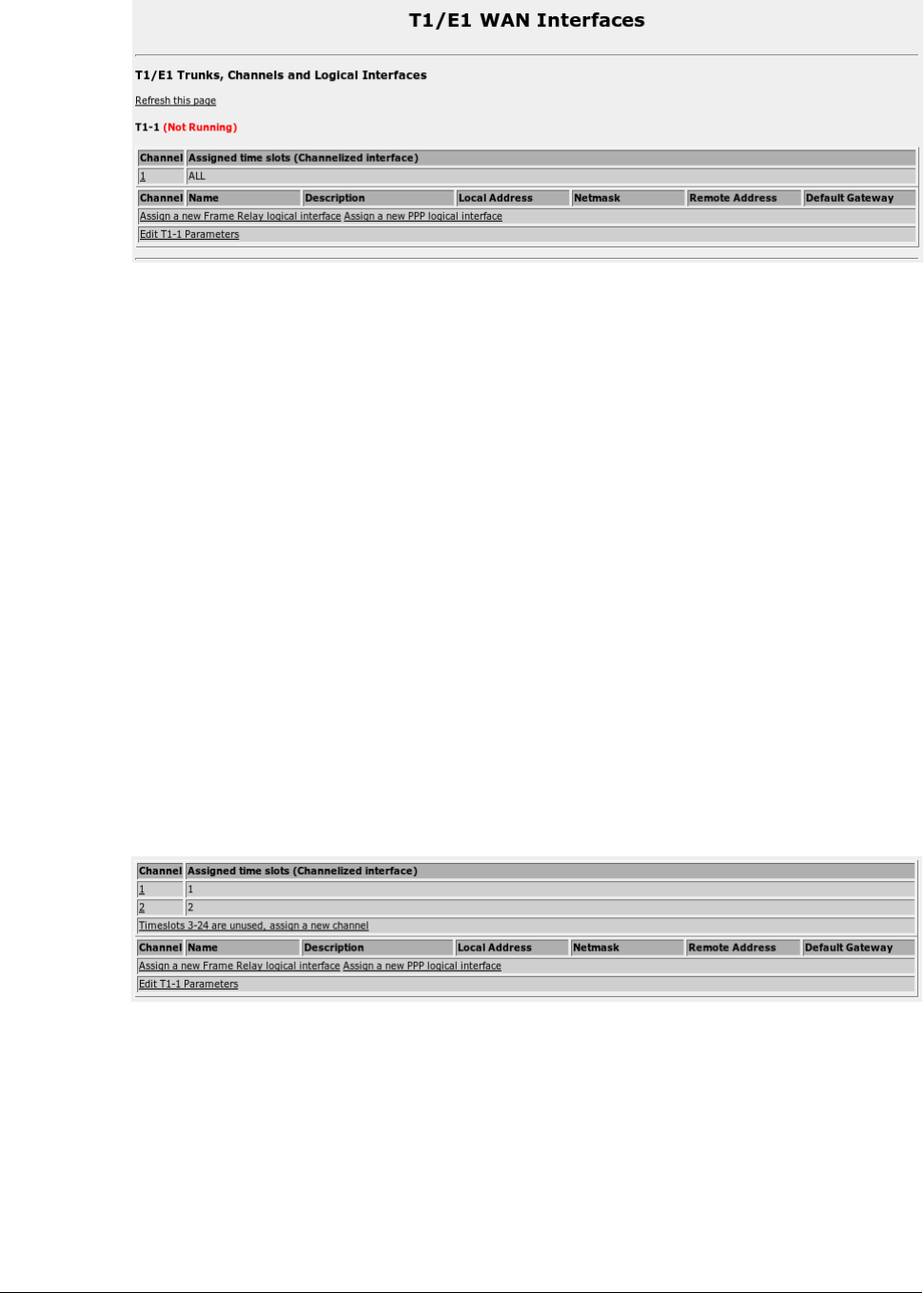
Figure 51: T1/E1 Network Interfaces Initial Configuration
This menu allows you to display and configure T1/E1 Trunk parameters, Channels
and the logical interfaces that run on them. A table is presented for each interface.
Note that the interface number is the same regardless of whether it is a T1 or E1
interface. Interface numbers are as described by the “WAN” labels as shown in the
home page chassis diagram.
The status of the trunks physical and logical interfaces are shown This menu presents
connection statuses but does not update them in real time. Click on the Refresh this
page link to update to the current status.
Strategy For Creating Interfaces
Initially, each interface will be configured as T1 and will have a single channel that
includes all timeslots (1-24). Channelized cards can have their timeslots reassigned to
make additional channels. Unchannelized cards may have timeslots removed from
their single timeslot.
If the interface is to be an E1, convert it using the “Edit T1-1 Parameters” link.
If the interface is channelized and you need to have more than one channel, construct
the channel groups with the desired bandwidths. This can be done by editing the
single initially configured channel and removing timeslots. The unassigned timeslots
will be displayed on the main menu in a link that creates channels, as shown below.
Figure 52: T1/E1 Network Interfaces After Channel Creation
Once all timeslots have been assigned to channels, the “Timeslots..” link will no
longer appear. Note that you do not have to assign all timeslots.
Assign Frame Relay or PPP to the channels by following the “Assign .. Protocol”
links. The resultant menus will allow you select the desired channel.
If you are assigning multiple DLCIs, assign the first DLCI used by that interface and
configure the Frame Relay Link Parameters and that DLCIs network parameters.
RuggedCom 67
