6-4
ROUTING SWITCHER SYSTEM (E)
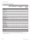
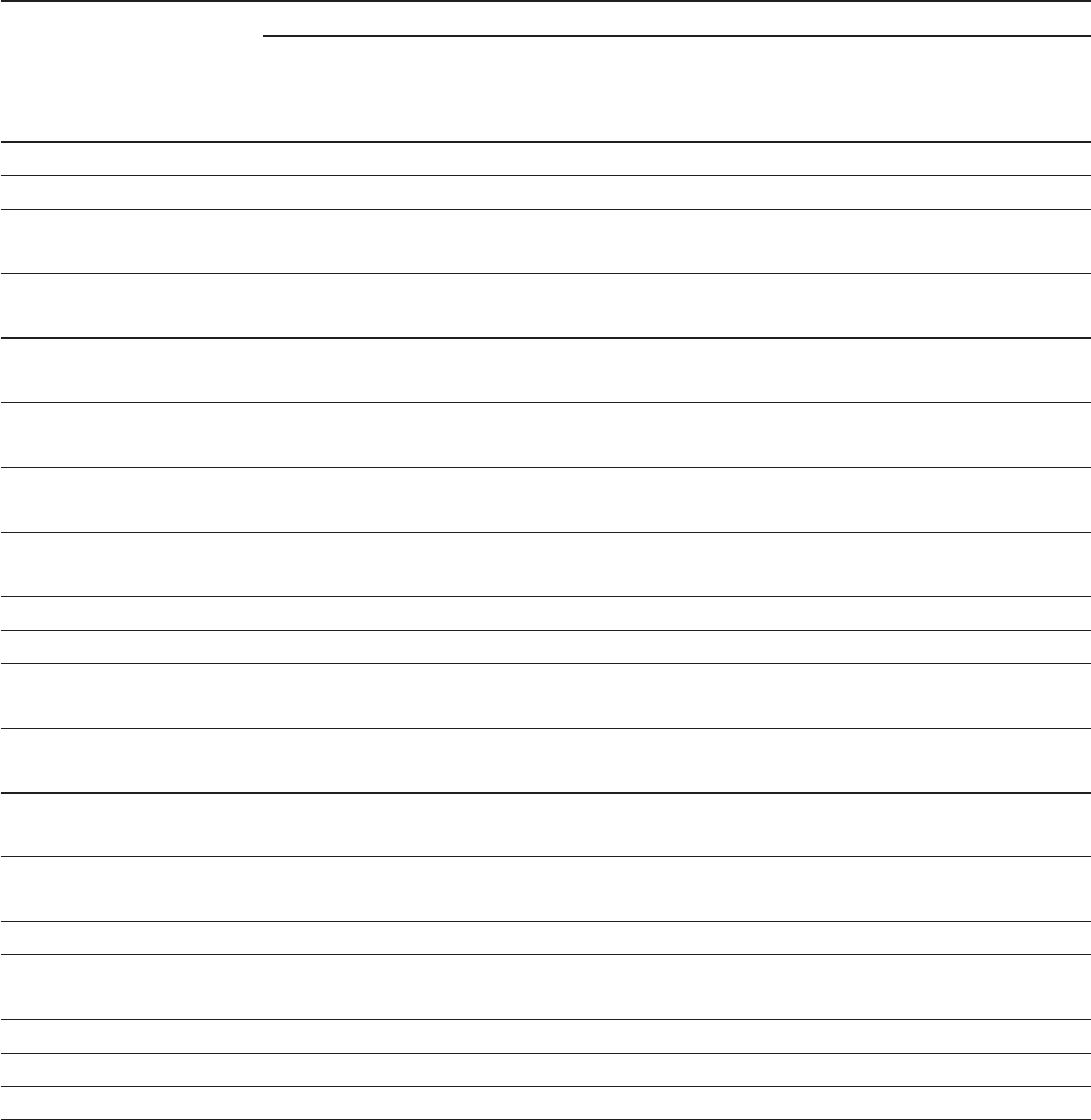
6-4. Diagnosis Items for Each Model
6-4. Diagnosis Items for Each Model
Self-diagnosis Items Error Display Model
**
**
*1
Status Status
**
**
*1
Error No. DVS-V1616 DVS-V3232B DVS-A3232 DVS-R1616
Indicator display Indicator DVS-V6464B DVS-TC3232
HDS-V3232 BVS-V323
BVS-A3232
Checking normal operations O_OOOOO
Detecting sync signals OOOOOOO
Detecting the sync signals __O__ O_
of the timing generator
Sync signal lock function __O__ O_
of the timing generator
OK/NG of crosspoint OOOOO OO
hardware
Unit’s internal temperature/ OOOOO OO
Fan’s driving condition
Detecting disconnection in OOOOO OO
the S-BUS data link
Communicating condition with _O__O__
Secondary stations
ROM/RAM/EEPROM check _OOOOOO
Re-start display _O_OOOO
Display of input/output _O__O
*2
OO
board insertion
Display of input/output _O_OO
*2
OO
board no-insertion
Communicating condition __OO_ OO
of REMOTE2/RS-422A
Communicating condition __OO_ OO
of REMOTE3/RS-232C
Backup memory setting data __OOOOO
Set-up of backup power OO__OOO
supply
Start-up back-up CPU board OOO_O OO
CPU board operations OOO_O OO
Timer stop _O__O__
*1 : HDS-V3232 does not have run diagnostics check on Status indicator and Error No. indicator.
*2 : HDS-V3232 is valid only when has been not inserted the input/output board, when input/output board insertion/no-
insertion will be displayed.


