4-20
ROUTING SWITCHER SYSTEM (E)
4-4. Basic Setup Procedures
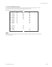
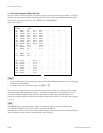
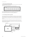
SET INHIBIT TABLE
DEST. SOURCE
001 01--08 09--16 17--24 25--32 33--40 41--48 49--56
VTR001 -X-XXXXX XXXXXXXX XXXXXXXX XXXXXXXX XXXXXXXX XXXXXXXX XXXXXXXX
VTR002 XXX-XXXX XXXXXXXX XXXXXXXX XXXXXXXX XXXXXXXX XXXXXXXX XXXXXXXX
VTR003 XXXX-XXX XXXXXXXX XXXXXXXX XXXXXXXX XXXXXXXX XXXXXXXX XXXXXXXX
VTR004 XXXXX-XX XXXXXXXX XXXXXXXX XXXXXXXX XXXXXXXX XXXXXXXX XXXXXXXX
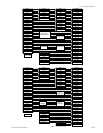
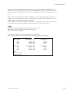
DVS-V3232B V2.10 STATION NUMBER 1
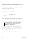
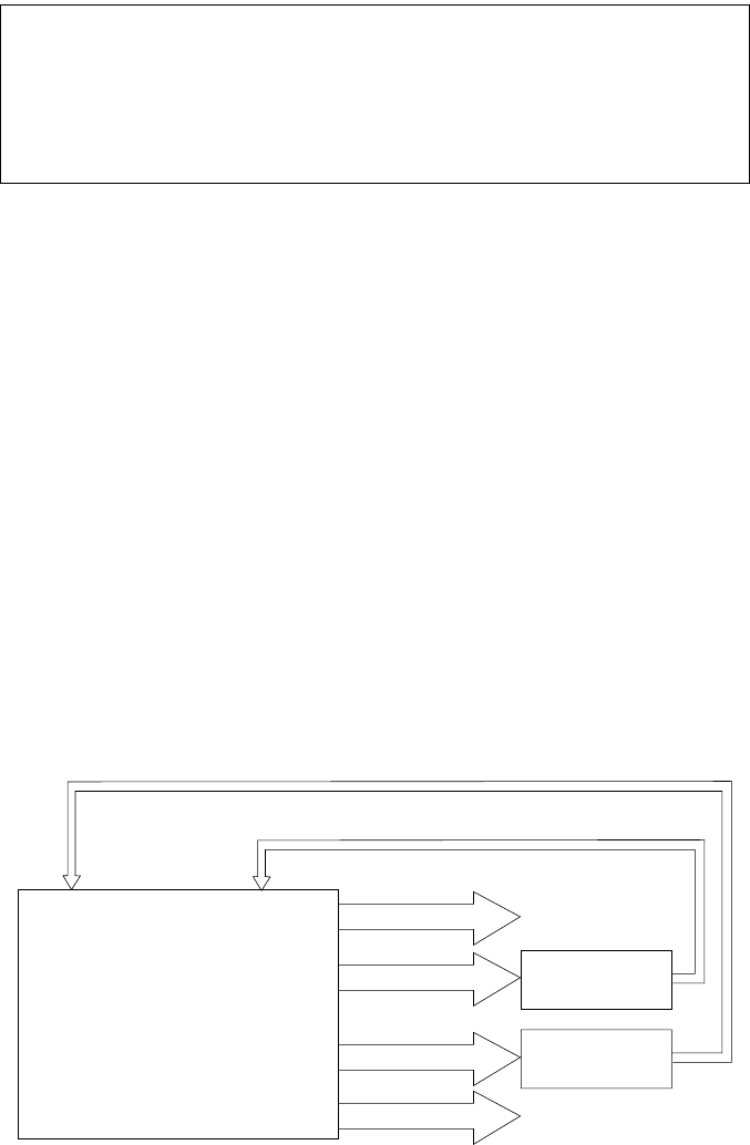
SDI Router
with both
4:2:2 & 4fsc
4:2:2 to 4fsc
Converter
4:2:2 Inputs
4:2:2 Outputs
4:2:2 Outputs
4fsc Outputs
4fsc Outputs
4fsc to 4:2:2
Converter
4fsc Inputs
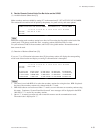
7. Inhibit Crosspoint Table (Menu Item [M])
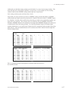
Set invalid crosspoint table for the specified crosspoints that will not be allowed to be selected by various
outputs INHIBIT TABLE on the primary station.
On the table “X” means valid crosspoint, and “_” means invalid crosspoint.
Be careful that destination cannot select a source which makes up a loop in which the destination be-
comes the signal generating source in order to avoid potential operational mistake.
In the example here the output VTR001 can not select input 1 (VTR001), etc.
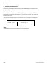
8. Tie Line Management (Menu Items [N] & [O])
This comes into play mainly if you have different types of serial digital data. Such as having both 4fsc,
and 4:2:2 signal streams in the same routing switcher level. By using the menu item [R : CALL SEC-
ONDARY STATION] you can have the primary call itself, and configure the primary to handle either
standard in groups of 8 inputs, and outputs. The same can be done be calling secondary stations on the
same level.
If you have both types of signal you probably need to convert from one standard to the other often. To
prevent the need to have many converters, you can set up the system recursively re-route serial data of
one type back into the routing switcher with a limited number of converters between routing switcher out
and routing switcher in. (See figure 8.)
Fig. 8


